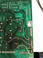
Demo of the 'Japan' solder sucker....
I have used 3 different techniques.
First-
Use fresh solder on the solder pads on the lower side of the header pins, then re-heat and suck. If you are lucky the whole header may just fall out the board as one. If it needs anything more then a little wiggle to extract, try and isolate the stubborn pins and re-solder and re-suck it. If only one stubborn pin is left just heat the single pin and gently pull the header.
Second- Only works on nylon header strips.
Secure the board on its side so you have access with the solder weapon (gun/iron) to the pads and you also have a comfortable position to use small pliers to pull the pins.
Add fresh solder to the pin pads then start on one pin and heat it. Do not hold the pin whilst doing the heating as the pliers will act as a heat sink and stop the process working.
Keep heating the pin until you can gently push the pin inwards towards the board with the soldering iron. At this point the solder securing the pin and the nylon body of the header have melted. Keep the heat on and use the pliers to gently pull the pin all the way out through the board and the nylon. Repeat until the last pin where you just need to heat the solder and pull the pin and nylon together.
Third- Used on heatproof headers.
Add fresh solder to all header pads, you need the pins to be secure otherwise the board may be damaged. Then use a suitable heavy pair of wire cutters to cut the header pins off as close to the base as possible.
Once all pins are cut use a file or similar to remove any burs from the pins. Then use a small screwdriver to gently but firmly lift the header pin retainer off the pins. Use a bit of card to add leverage and project the board from scratches. Once the header retaining strip is off you can just heat and remove the pins one by one.
There is a fourth method mentioned above that involves cutting the header strips into individual pin sections but I have never done this as not had any soft enough to cut.
After removing the headers I like to re-flow solder over all the empty holes top and bottom and re-suck them just to clean them up and make sure they are ready to receive the new pins.
The whole process can be complicated by any previous work done on the board as different solder types react differently and if you have a mix of types it can be a pain to remove the pins so a good clean up of all the old gunk and new solder makes adding the new ones a painless process.
Once you got the new ones on, clean up with isopropyl alcohol and check your work visually, then with a meter and then check it all again once you have had a cuppa.
Forgot about this hand/finger drill...
https://www.amazon.co.uk/Pieces-Pre...514613&sr=8-2-spons&keywords=hand+drill&psc=1
If you have a damaged board where the through tube (the metal lining in the hole in the PCB) has been damaged or folded, no amount of solder heating or sucking is going to help. Only option I have found is using a handheld drill as linked above.
Good luck.


