What's new
Pinball info

Register a free account today to become a member! Once signed in, you'll be able to participate on this site by adding your own topics and posts, as well as connect with other members through your own private inbox!

Guess what… CORVETTE

Yes,it would as the motor board drives the engine. Does it boot up without further issues then?
I am just working from the manual, dont have a machine. Looks like motor board, slave motor board are driven directly from the CPU, the feedback is via a separate opto board in the engine. There are two hall sensors but dont think they are fed back. The car track is driven via the PDB and a two motor board. What is the number of the switch you connected on the ramp?
 
Sorry, didn‘t press send this morning. if changing the PDB made it better for a bit I‘d suspect the ribbon cable between CPU and PDB. Measure the voltages on the CPU board and see if they are ok there.
 
Thanks drhex. I’ve checked the 5v leaving the cpu at C31. From switch on it instantly went to 4.95v and was rock steady.
I haven’t tested 12v leaving the cpu, not sure where to measure that from leaving the board?

It was a ramp exit switch I used installed. Can’t recall the number (45 route 66 exit perhaps!) but I’ve tried Wayne’s advice and unplugged it. Still the same.

I will try a new short ribbon as i haven’t tried that.
Thanks mate
 
Tried three other short ribbons. No change.

Would NVRAM have anything to do with it?
 
Possible, but that is tested on boot. The machine is playable normally if you disconnect the master motor board?
 
Possible, but that is tested on boot. The machine is playable normally if you disconnect the master motor board?
As in the master motor board in the backbox?

I could try booting with that disconnected, the playing a game with those mechs disabled and plug it back in at the end of the game.

I’ve been playing a few games and noticed a load of lamp matrix problems.

I’m almost scared to ask 🫣
 
So i started a game with the engine board in backbox unplugged.

Sometimes the racetrack behaved normally sometimes it didn’t and did the thing when the motors kick in reverse.

Incidentally, if you start a game after it’s failed the LT5 test, it kicks two balls in to the shooter lane and the motors kick in reverse.

I’ve tried booting with the motor master unplugged. Motor slave unplugged and the dual motor board unplugged. It doesn’t make any odds.
 
What do you mean by doesn‘t make any odds? Thefestures should be disabled and the game should run?
 
As in, with the LT5 motor unplugged, the race track still misbehaved.
The ribbons were still plugged in though. Does that make as difference?

And vice versa, if I boot the game with the racetrack unplugged, the LT5 still misbehaved.

It’s random but on the occasions I tried this time, I couldn’t get the LT5 to pass test after I plugged everything back in after a game ended.

I’ll start videoing and posting the results here as maybe my explanation together with others knowledge on the game isn’t clear.

Edit:
Just a note. I think from memory (certainly this morning) switch on from cold after a prolonged period of being off, it boots first time and passes test.
As soon as I open and close the coin door, which prompts a retest of both mechs, they fail.)
 
Last edited:
But the rest of the game works fine, ie no issues with switches, coils, resets etc? The optos in the Engine and racetrack are clean and not bouncing in switch test? Did you get the other CPU to test?
 
But the rest of the game works fine, ie no issues with switches, coils, resets etc? The optos in the Engine and racetrack are clean and not bouncing in switch test? Did you get the other CPU to test?
No everything is fine.
When it hasn’t passed its self tests and you start a game, it spits two balls in to the shooter lane and the racetrack motors spin in reverse for a bit. Then it’s fine.
CPU has just been delivered by the postie so I’ll be trying that this evening once I’ve plucked up the courage to swap the asic over !!!
 
Empty all balls, go into switch test and make sure that all the optos in the trough are working correctly. It spitting out two balls makes me think that you still may have a switch issue somewhere. How do the racetrack motors spin with the motor boards disconnected?
 
It’s confusing because there’s the “Motor master board” which is for the LT5.
And the “Duel motor board” for the racetrack.

So I tried it with LT5 board disconnected to see if the racetrack behaved. And vice versa. But it made no difference.

The trough optos test fine, it’s just a weird anomaly it does when you start a game of the LT5 fails test.
It spits 2 balls out and kicks the motors in to spinning in reverse.
 
Wonder why they would put that into the code... If it plays fine afterwards it probably isn't the fault. Let's see what it does with the other CPU.
 
Ok so tried another cpu. Transfered the chips over.
No change.
Pretty gutted.

Could it be a corrupted Rom?
I’ve tried the original code Rom it didn’t make any difference.
How about U22?

It might be easier to try that rather than borrowing my mates machine which is a 4 hour round trip at least.
 
I can burn you a ROM but that is checksum checked and should be OK. Still think this will be switches in some way. Please connect everything, go into switch test and make sure that with balls out all the shaded switches are closed and everything else is open. Then put the balls in and see if only the expected switches are opened.
 
Ok, I removed the balls and checked all the greyed out switches and they all checked out. The switches are good.

It just gets more and more random.

I’ve played through plenty of game this evening with no problems and then equally it’s misbehaved. I think once you get it passed all the tests it’ll play flawlessly until you power cycle it or open the coin door.

I’ve even gone down a rabbit hole with the coin door interlock switch and door open switch.

Is it worth removing the caps off the slave board and checking for leaks?

I think I’m just going to have to borrow Jon’s corvette and systematically swap boards until the problem disappears.

And to top it off tonight the loop gate coil I replaced the other day stopped working.
It has voltage at both sides, so guessing it’s a driver issue but not got time to check.
 
If it has voltage on both sides it is cable or driver. If you can swap boards it should solve this. You can send me the box otherwise and I’ll look here.
 
I’m like Clark Griswold at the moment when his Xmas lights won’t work!

So I’ve put the kids to bed and come back out for more testing.

Q44 which drives the loop gate test fine.

In coil test you can hear a slight pulsing from the coil. Like it wants to move.
I then went and checked the diode beneath Q44. It reads 0.293 in both directions. That doesn’t seem right to me. What say you.

Ive also swapped the long ribbon between slave and master end over end and 4 out 4 times it’s passed test on boot!!

Watch this space.

It can’t be that simple………. Can it?
 
Last edited:
  • Like
Reactions: JT.
Yes, can very well be the flat cable or the headers on the board. Their solder likes to crack, also the mating surfaces corrodewhere the fingers of the plug sit. If you turn the cable over you mate different places which fixes it for a while. Get a new one and replace the headers if you want to be sure.
The snubber diode is across the coil, you’re measuring the coil resistance. You need to disconnect J127 and/or J128 to measure it. Just ground the switched side of the coil to test it. The plunger is moving freely?
 
Now you mention it I’m suspecting headers on the board.

The master board headers are the ones I replaced and tore a trace.

The ribbon is brand new but I guess it still could be that
As for the coil..

It’s one of those tiny coils for gates. So no plunger or sleeve etc..
I’m not sure i fully understand your instructions… sorry 🙈.
What should the resistance be? It doesn’t have a diode on it.
Funny because the same coil on another gate has the diode on the coil. This coil doesn’t have a diode. Should it?
 
Last edited:
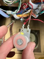
Here’s a pic of the coil.
Am I correct in saying it doesn’t matter which way it’s wired?
And which side should the band of the diode go.IMG_5441.webp
 
The loop gate coil is driven from the low power drivers transistors on the Power Driver board. It gets its supply from J107 pin 3. This supply is also used by things like the slingshots and jet bumpers. If they work OK then it is likely the supply is good.
The other side of the coil connects to the Power Driver board at J127 pin 9.

Assuming this is a new coil (and you can measure a resistance across the terminals when it is not connected), then the problem is likely to be the power driver board wiring/connections or the driver section (using TIP102 Q44) on the Power Driver board.

It is correct that the coil doesn't have a diode on it - there is a diode on the power driver board that handles the back EMF when the coil turns off. If you remove the connections from the coil/power driver board, you will read a resistance of a few ohms regardless of which way round you put your meter.
It shouldn't matter which way round you wire the coil
 
Banded side to power, i.e. the red cable. Diodes were moved to the PDB on WPC so you don't need a diode on the coil itself. The diode is there to "snub" the voltage spike which happens when you switch the coil off - the energy stored in the electromagnetic field is induced into the wiring when the power is switched off. This creates a big voltage spike, similar to what happens in the ignition coil in your car. This will destroy the driver transistor over time. The diode essentially shorts the coil out for the induced spike thereby protecting the driver.
 
  • Like
Reactions: JT.
Diodes were moved to the PDB to make pin technician's work easier - they didn't have to worry about connecting coils the right way round anymore.
So with J127 connected you're measuring the coil resistance instead of the diode as the diode is across the coil. That resistance is the same both ways and much smaller than the diodes, both in blocking and non blocking direction. You therefore need to open the connection to the coil by unplugging J127 to measure the diode. It is easier though to ground the brown cable at the coil (which is the same thing Q44 does) and see if it pulls in. The armature can move freely? Given you have power on both lugs it is unlikely the coil is broken (it must conduct for that to happen).
 
Thanks mate.
So something on my board is killing the coil. That’s 2 now.
£20 a throw. It’s working for a while when it’s installed.
I’m drawing stumps now and sending the boards off.
Thanks for everyone’s assistance in this. I really appreciate you all taking the time to go and download the manual and try and figure this out for me. A complete stranger.
You’re what makes this forum amazing.

I’ll update when the everything is fixed and what the issue was
 
  • Like
Reactions: JT.
If this is the last remaining issue we should be able to find it. What makes you think that the board is killing the coil? And is it dead for sure? The board can only switch ground to it which should be fine. And always happy to help.
 
  • Like
Reactions: JT.
Well, we still have the same issue of the lt5 and racetrack. It started acting up again.

But yeah the coil is now showing open line.
 
Ah OK, that isn't good. Pretty sure now this is caused by the headers or flat cable on motor or slave board. Have you reflowed the solder on the slave board? Coil open: How did that happen? Coil wire still connected at the lugs? It is an A-14406?
 
Back
Top Bottom