D
Pinball info
You are using an out of date browser. It may not display this or other websites correctly.
You should upgrade or use an alternative browser.
You should upgrade or use an alternative browser.
Flash Gordon light fault (and now whole game not working!)
- Thread starter VeeMonroe
- Start date
D
Deleted member 5505
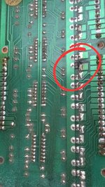
Just cleaned it a bit, the trace between Pin 17 and Q12 base pin is broken and appears to be the one that has frazzled at somepoint.
Q12 reading is off in comparison with the other scr's; should I be checking higher up the food chain before replacing Q12 and jumper the break?
Q12 reading is off in comparison with the other scr's; should I be checking higher up the food chain before replacing Q12 and jumper the break?
Last edited by a moderator:
officially: repair the break first. the retest Q12. they can well read different to others if not wired into a similar circuit. if it’s still not testing similar then replace. unofficially: just replace it and fix the broken trace all at the same time. faster total fix time.
D
Deleted member 5505
Cheers Alan, I’ll probably go with the official method first as I’ve not got any Scr’s just a boat load of transistors. Will order a set
D
Deleted member 5505
Jumpering alone didn't resolve, moved an unused (for this game) SCR over and now Q12 Pin 17 fine bulb flashing @ left 15 sec insert.
Shoot again flashes in test mode, but not attract currently and haven't spotted it working in game yet so will investigate.
Another few inserts have decided to be intermittent with all the playfield manoeuvring this week, will investigate tomorrow.
Shoot again flashes in test mode, but not attract currently and haven't spotted it working in game yet so will investigate.
Another few inserts have decided to be intermittent with all the playfield manoeuvring this week, will investigate tomorrow.
D
Deleted member 5505
After resolving left 15 sec insert (above) I switched the original board back in, interestingly.you have two lamp driver boards. do all the same problems occur with either board , or is one better than the other?
Both boards: 20,000 & Extra ball inserts are out (Have seen these working previously so possibly holder issue but will check everything)
Replacement board: Mini bonus 8 is off (new bulb holder, this had worked the other day)
Old board: Mini bonus 9 off and Mini 8 bonus is locked on !?!
Bit perplexed by that outcome, I didn't touch the playfield between testing both back to back.
shoot again never lights in attract mode, but if it works in self test mode it’s all good
pm meyup, @AlanJ can you send me a price for your device, an LED display kit and a ton of bulb holders please, Oh and do you need a squawk and talk for part-ex

D
Deleted member 5505
Flash must be getting some serious deja vu  just blew F4 trying to fix bulbs .....
D
Deleted member 5505
Head scratching time.... 20k saucer is locking on (checked old board, this flashes correctly so assumed the SCR needs replacing on the replacement board)
Q21 is testing fine all the way to the tip of the pin, R21 is fine too. What am I missing ?
Q21 is testing fine all the way to the tip of the pin, R21 is fine too. What am I missing ?
D
Deleted member 5505
3 new SCRs and 3 more bulb holders all inserts are currently working.
There’s 1 GI out but that’s a balls up I made which I’ll repair when I’ve got more patience
There’s 1 GI out but that’s a balls up I made which I’ll repair when I’ve got more patience
D
Deleted member 5505
Ohh, just played the game and the flippers are each triggering 10k mini bonus advance. Will have to work out which switch it is doh
Edit
No switch issues on self test, the sound FX appears to be the same as the single drop target. Which seems to score 10k and advance 2 on bonus
Edit
No switch issues on self test, the sound FX appears to be the same as the single drop target. Which seems to score 10k and advance 2 on bonus
Last edited by a moderator:
D
Deleted member 5505
and the 15 seconds clock inserts are both on solidly, sweet baby jebus.
Edit reseated aux lamp and has resolved for now
Edit reseated aux lamp and has resolved for now
Last edited by a moderator:
D
Deleted member 5505
As of a few minutes ago, after another new SCR soldered to the lamp board and another new bulb holder everything is working 
Fingers crossed it's the last post in here.
Fingers crossed it's the last post in here.
D
Deleted member 5505
Oh that didn’t last an hour.
All GI is out now in game and test.
All GI is out now in game and test.
D
Deleted member 5505
MPU giving 6 flashes after the boot pause.
No voltage along the GI common wire? Not sure if it’s called the same as the insert common wire. Sorry
No voltage along the GI common wire? Not sure if it’s called the same as the insert common wire. Sorry
D
Deleted member 5505
F5 blown, 15a was fitted instead of 20a. 20a back in, few bulbs out though
D
Deleted member 5505
Seems to be predominantly left side of the GI and back that are still out, front and right are now on
D
Deleted member 5505
Struggling to identify the issue, all fuses checked, the GI is all working in the back box and everything on the right hand side of the playfield, and the coin door bulbs are on too.
x6 playfield GI bulbs on the left are out, along with the two roll overs in the top left hand corner and the left hand pop bumper light. Those 3 are always on under normal conditions.
x6 playfield GI bulbs on the left are out, along with the two roll overs in the top left hand corner and the left hand pop bumper light. Those 3 are always on under normal conditions.
Last edited by a moderator:
A broken GI wire to the left side of the playfield.
D
Deleted member 5505
Thanks Alan, I was looking for anything remotely like that last night. Bits that looked iffy I resoldered or repaired. If it’s a broken wire, it only took affect after everything being fine for 30-60mins with the playfield down.A broken GI wire to the left side of the playfield.
Should be easy enough to find - check continuity to the part of the GI on the right side that is working ok. It may well be that there are two circuits of GI - in which case, maybe you have a whole section out?Thanks Alan, I was looking for anything remotely like that last night. Bits that looked iffy I resoldered or repaired. If it’s a broken wire, it only took affect after everything being fine for 30-60mins with the playfield down.
The 2 GI Circuits are Colour coded usually like this:
Circuit 1 - Red wire and a White wire
Circuit 2 - Green Wire and an Orange wire
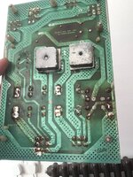
In some games, the GI is controlled (just like the feature lights), this is so it can be dimmed, flashed etc. I cant remember if FG has that? The tell tale sign is a large metal thyristor (or 2) bolted to the metal plate in the cabinet that houses the transformer and rectifier board.
D
Deleted member 5505
Fortunately no thyristors near the rectifier board.Should be easy enough to find - check continuity to the part of the GI on the right side that is working ok. It may well be that there are two circuits of GI - in which case, maybe you have a whole section out?
The 2 GI Circuits are Colour coded usually like this:
Circuit 1 - Red wire and a White wire
Circuit 2 - Green Wire and an Orange wire
In some games, the GI is controlled (just like the feature lights), this is so it can be dimmed, flashed etc. I cant remember if FG has that? The tell tale sign is a large metal thyristor (or 2) bolted to the metal plate in the cabinet that houses the transformer and rectifier board.
Taking readings from the daisy chain of GI that is working Im getting negative readings.
The daisy chain that isn’t working seems to be getting very warm.
D
Deleted member 5505
Rectifier readings with unplugged output
Tp1 - 7.5
Tp2 - 150
Tp3 - 12
Tp4 - 6.6 ac
Tp5 - 43.7
Tp1 - 7.5
Tp2 - 150
Tp3 - 12
Tp4 - 6.6 ac
Tp5 - 43.7
D
Deleted member 5505
Something short circuited.
D
Deleted member 5505
Ok, thanks Alan. Are those rectifier test points ok or is that toast? cheersSomething short circuited.


