What's new
Pinball info

Register a free account today to become a member! Once signed in, you'll be able to participate on this site by adding your own topics and posts, as well as connect with other members through your own private inbox!

Complete Elektra restoration

Had my first few games on Elektra now its all back together and turned the volume way up on my new s&t sound board. Man it sounds and plays nice :)

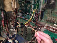
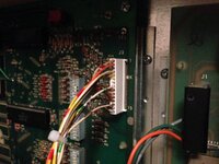
I had a few lamps out, not working after putting everything back together, which is usually a combination of dead lamp driver scr's, blown bulbs (even though all new - they blow with a white haze sometimes), and bad connectors. Took the lamp driver out to inspect and found some pretty bad try joints on all 4 connectors. Pics below of after i'd sucked the solder off all offending pads, ready for reflowing them.

So now, i have all but 1 lamp working :) Probably the socket ;)

Also been adjusting a few contacts here and there, slingshots switch spacing and also raising the angle slightly. I was wondering if anyone knows the ofificial pitch level for early 80s games. it is 5.5 degs?

Another question to ponder to. What is the point of using half mcr106 drivers and half 2n5060 drivers? Why have some using a bigger, more powerful device? They are all single lamp, or single feeds to other relay boards. Did bally envisage something more powerful being used in terms of lamps, but never realised???

LED it dude. LED the living daylights outta that thing! :D
 
Often the mcr 106s are used to drive two lamps at the same time. Usually something like shoot, again , one on playfield and repeat on backbox. Or specials at both outlanes. Agree there's probably too many.
 
I read something semi-official, probably an interview with a Bally designer, about the mix of SCRs. It was, as @pinballmania suggested, to allow driving more than one lamp per circuit, e.g., a pair of SPECIAL lamps. I'll try and find it. I guess when the board was designed they tried to make it as future proof as possible. It certainly lasted quite a while!

I'm going to agree with @pinballmania and @Pudsey pinball on this one: stick with incandescent. That PF is so beautiful it needs the warm glow of lamps to bring out the colours. I'm not anti-LED as I'm going to switch to LEDs on VECTOR, but just like PARAGON I don't think LEDs would suit ELEKTRA.

Keep up the good work!
 
Booooooo to all the LED haters! :D

I mean look how beautiful this looks:


Agreed. After spending all this time doing an authentic Restoration would be sacrilege to ruin it with LEDs.

On the contrary, I think after spending a lot of time on a restore it's insanity to put incandescent's in when they a) don't last 5 minutes, b) stress old circuit boards which were not well engineered enough to handle the current they draw, and c) slowly cook everything around them - especially backglasses.

My opinion on incandescent's is that it's over for them, they're done and finished. By a long time. A long time! 5-6 years ago it was acceptable to be on the fence and sitll use them sometimes, but now, in 2015? No. At the very least you should be taking the GI circuits off incandescent.

But, it's an opinion and that's all it is. Do what you want to do, and enjoy the fruits of your labour! :thumbs:

Oh also, doesn't Pinball Mania sell some kind of advanced warm LED which closely mimick the incandescent bulbs? I've never tried them but certainly curious.
 
You just need to get a mixture of the two, it's hard to get right but if you do it looks the nuts.
 
I would have said - Wrong! I have yet to see a decent GI bulb that will replace an incandescent and that doesnt flicker unfortunately..
 
I would have said - Wrong! I have yet to see a decent GI bulb that will replace an incandescent and that doesnt flicker unfortunately..

That's usually down to cheap/poor quality bulbs which don't have some kind of rectifier or capacitor built in. Because the lamp circuits are runing on AC, when you put a DC LED in it only runs on half of the AC frequency, which causes the flicker.

The "noflix" bulbs from Pinball Center are the best ones to use. Here's a page on their site with a video which explains it: http://www.pinballcenter.eu/english/product-informations/noflix-advantages/
 
Really?? I have seen noflix (not even GI) in RFM and they flicker like crap....
 
Please can we move the led chat somewhere else. It's getying abit off topic. This thread is about my elektra restoration and I don't use leds. Thanks
 
Really?? I have seen noflix (not even GI) in RFM and they flicker like crap....

That's unusual. They're can't have been noflix led's surely? I've used them lots and done a side by side comparison, and they're definitely better.

Speaking of RFM, the one I'm busy restoring is gonna get the NoFlix Plus bulbs so maybe I'll shoot a video with high shutter speed so we can critique them.

Please can we move the led chat somewhere else. It's getying abit off topic. This thread is about my elektra restoration and I don't use leds. Thanks

Yes boss!
 
Been doing more play testing now the playfield is back together. More switch issues being resolved. I fitted all new caps to the switches that I changed for new ( all standups) but I didn't notice until recently that some other switches such as some top playfield rollovers had original ones, or missing ones. In its previous life someone had removed most of the original caps, most likely due to them failing and causing random activations.

So I'm now going through all remaining switches and updating all caps. What happens without them is they work when you test in switch test (normally) but are missed when the ball activates them quickly, hence the need for a cap to extend the time the cpu 'sees' the switch.

Also , a switch row decided to stop responding after a few games so need to investigate this. Often niggles suffice quickly like this within a few hours play as everything settles in. This is also why a good soak test is always needed on any restoration once the reassembly is finished
 
What value and type of capacitor do you fit across the switches? A quick look in my Vector manual and it says .05 MFD. I assume ceramic disc, 16V.
 
Had a little time this weekend to investigate my switch matrix issue now the playfield is all back together. I started by replacing the bad repair on the cabling done by a previous owner.

Before

IMG_3611.JPG

After

IMG_3613.JPG

Unfortunately, this did not cure the issue. So, i carried on investigating.

The problem was sometimes during a game one of the return lines would go dead and all switches on that return would become non responsive. However, the fault was intermittent and so isolating it was proving difficult. Investigation of the manual and switch matrix diagrams showed an empty position at the start of the return. Now, from previous knowledge i know that these empty switch positions are usually cabinet switches. For some unknown reason Bally decided not to print the cabinet switch positions on the matrix diagram, so they look at first glance the same as any unused ones. Great, let's make it just a little more difficult! So, after some studying i worked out the unmarked switch was the start button. Now the start button has always worked ok itself, but i had look at it in more detail and put the game into switch test to hilight any issues. On close inspection the diode for the start button switch and possibly one of the switch lugs was shorting to the ground of the coin door metal work. I also checked the fish paper for any wear and cleaned the contacts whilst it was removed.

Now the games' switch matrix is all sorted and plays perfectly :)
 
A-ha! The old start-button-shorted-on-the-coin-door trick! Soon you'll have some fresh fishpaper if needed ;)

It is irksome that these switches aren't included in the switch matric diagram in the manual. I guess it's a sign of the times. The schematics are 30-40 years old and the originals maintained by hand on real pieces of paper; the manual merely being "photocopied" reproductions. Today we'd knock up a revision in CAD.

It always seems to be that whenever I need to trace a wiring fault I have to unfols at least three of the schematic sheets at the back of the manual! For PARAGON I reprinted them on A2 sheets which makes them easier to read and doesn't matter if they get dirty or damaged.

Sorry, nice work on ELEKTRA ;) Looking good!

Yes, the only way to fill in the blanks as it were, is to check the playfield switch number diagram and then count them on the matrix. One handy thing is though, i believe the cabinet switches are fixed and don't move game to game so you only need to do it once. Maybe when i get a minute i'll create a more complete electronic diagram to share.
 
Seems to depend a lot on the game.

My VECTOR manual depicts a switch and diode in all 48 positions (8 rows, 6 cols) on the switch matrix, but doesn't label 6, 7, 9, 10, 11, 16, 20, 25, 32 and 41-45 where 6 = CREDIT BUTTON, 9/10/11 = COIN 3/1/2 and 16 = SLAM.

GOLD BALL is different again in that the switch matrix diagram is incomplete (and it's only 8 rows by 4 cols). Switches 5, 6, 9, 10 ,11, 16 and 32 are absent, but 5 = RIGHT FLIPPER BUTTON (for rollover lane cycling), 6 = CREDIT BUTTON, 9/10/11 = COIN 3/1/2 and 16 = SLAM are listed in the switch number assignments.

Similar again in PARAGON. An 8 row by 5 col matrix, all switches and diodes indicated in the schematic but not all labelled in comparison to the switch number assignments. Same again with 6, 9, 10, 11, 16 and 32. Is 32 always unused?
 
The switch matrix stumped me so I wrote a table of it including the wire colours are, which junction terminal they are connected to, whats on the playfiled (green) vs cabinet (red) etc. Have actually found it very useful - see attached. Perhaps I should put this in the Technical Resources forum as my give back to the community.
 

Attachments

  • Gold Ball Switch Matrix.pdf
    191.9 KB · Views: 8
Played my first few proper games on my completed elektra playfield this last week and now I have the settings set correctly (by reading the manual no less!) it's amazing! What a game. 3 different ways to get Multiball and a sudden death lower playfield with a superb bonus rule set :)
 
Back
Top Bottom