Pinball info
You are using an out of date browser. It may not display this or other websites correctly.
You should upgrade or use an alternative browser.
You should upgrade or use an alternative browser.
Bally / Stern SS's get into the 21st Century - Introducing "ColourClassic" Score Displays
- Thread starter AlanJ
- Start date
OP
OP
ty. i’ll tackle the learning curve to switch over at some point - my poor old brainThat's the platformio command line
Honestly though, have a think about getting setup in platformio & vscode - you'll never look back.

OP
OP
Cheers Davey, you may live to regret that offerI know, it seems like a massive jump, but it's a totally worthwhile one. Hit me up if you need a steer.
OP
OP
I’ve finally got round to progressing this project. I’ve had the new hardware pcbs sat in a box unopened on my desk since June, so decided to open and crack on with the work.

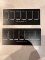
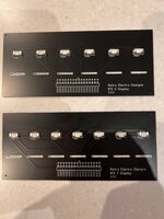
I’ve got a revised base controller pcb and finalised 6 and 7 digit display boards.
I made up a new controller and made sure it works, which it does.
Spent a lot of time working on the code to speed up the score display refresh, especially when using .jpg images when the game switches between last game score and HSTD. I’ve got it going as fast as I can achieve now, and it’s fast enough.
Next job is to create and store a set of parameters - eg what display pattern, colour, whether it changes or not over time.
I’ve decided to allow a setting whereby the colour or the type of display image changes over time, with a setting to say how often the change should happen.
All the settings are stored on the sd card, and I could be lazy and just say you need to remove the sd card and edit the file on a laptop to change the settings, but a much nicer option is to allow the settings to be changed using the button on the device - so that’s the next thing to look at.
The final thing to do will be to get the 5 separate score units to communicate with each other, so that the settings from the “master” unit can be transmitted to the other 4 “slave” units. That’s going to require the mac addresses of the units to be shared with each other.
So, loads of technical stuff to do. Hopefully I’ll have a full 5 unit demo system working within a week or 3
Attachments
Looking forward to some working pic’s Alan.
OP
OP
Quick videos. i’ve set it to change “font” every 20 seconds. you can decide if you want a fixed font or cycle through all fonts, or pick one at random. 21 jpeg fonts and then 4 different 7 segment fonts with a choice of 10 colours on each . so 61 different possibilities!!! more to come in future too:
Next video, how to setup and configure:
Next video, how to setup and configure:
Amazing Al! Somehow I missed this thread until now.
OP
OP
OP
OP
The development is over and we have a fully working system:
and
There is wifi communication between the 5 separate score displays, so that one of the units decides what “font” to display and sends the new font to the other 4 displays.
I’ve also added the ability for a unit to run without an sd card installed. (in this case it can display 40 different “rendered” 7-segment style fonts, but cannot display the jpeg files (which are on the sd card). This makes it a cheaper option for anyone not interested in jpeg images, but wants the colour choice flexibility. (The sd card reader is cheap, so i’d always recommend installing this on all boards). why? Because:
I’ve also added a software firmware update option. This auto upgrades the software if a new version is saved onto the sd card.
I’ve done a lot of testing on these, but still more tests to do.
Almost ready to offer these out as a “community” project for anyone who wants to build their own set.
I’ll publish a BOM - Bill of materials and typical costs. All the components are readily available, off the shelf, the only thing that isn’t are the two pcbs - the 6 or 7 digit display board pcb and the base controller board. I’ll get a batch of these produced once i’ve got an idea of demand.
I may also be able to source all the hardware parts into a kit if there is demand for that too?
The software will be made available to upload to your own board. Again I could pre-load this onto the esp32s if I’m supplying these.
Last edited:
The complete lack of support for old Williams solid states saddens me ")
OP
OP
Rome wasn’t built in a day……The complete lack of support for old Williams solid states saddens me
The bally games used the same display set for over 15 years, lots of games.
Williams display technology changed a bit more often.
Worse still, they used High voltage logic chips on the controller/ driver board so when you want to switch to low voltage led or tft displays, you have to replace the whole thing, a lot of work for me. On the plus side, there is only one controller board which talks to all the separate displays, so it could be quite easy to replace
OP
OP
BOM:
6 Digit Display Board:
6 Digit Display PCB with SMD Sockets pre-soldered 1
IPS 1.14" 8 pin SPI TFT Display 135X240 Pixels 6
2X16p Right angled Male Header 1
7 Digit Display Board:
7 Digit Display PCB with SMD Sockets pre-soldered 1
IPS 1.14" 8 pin SPI TFT Display 135X240 Pixels 7
2X16p Right angled Male Header 1
4 Digit Display Board (Credit/Match/Ball in Play):
6 Digit Display PCB with SMD Sockets pre-soldered 1
IPS 1.14" 8 pin SPI TFT Display 135X240 Pixels 4
2X16p Right angled Male Header 1
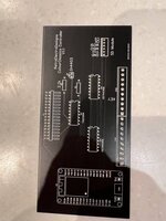
Base Controller Board:
Base Controller Board bare PCB 1
2X16p Female Header Socket 1
10p 3.96mm / 0.156" male header 2
15p Female Header Socket 2
Dil 16p IC socket 3
SN74HC165N Shift Register IC 2
SN74HC595N Shift Register IC 1
2N4403 / 2N3906 Transistor 1
10k Resistor 1
ESP32s Devkit Doit V1.0 Processor module 30 pin 1
Micro SD card reader board 1
Micro SD Card 128Mb 1
15cm double Sided foam tape 1
6 Digit Display Board:
6 Digit Display PCB with SMD Sockets pre-soldered 1
IPS 1.14" 8 pin SPI TFT Display 135X240 Pixels 6
2X16p Right angled Male Header 1
7 Digit Display Board:
7 Digit Display PCB with SMD Sockets pre-soldered 1
IPS 1.14" 8 pin SPI TFT Display 135X240 Pixels 7
2X16p Right angled Male Header 1
4 Digit Display Board (Credit/Match/Ball in Play):
6 Digit Display PCB with SMD Sockets pre-soldered 1
IPS 1.14" 8 pin SPI TFT Display 135X240 Pixels 4
2X16p Right angled Male Header 1
Base Controller Board:
Base Controller Board bare PCB 1
2X16p Female Header Socket 1
10p 3.96mm / 0.156" male header 2
15p Female Header Socket 2
Dil 16p IC socket 3
SN74HC165N Shift Register IC 2
SN74HC595N Shift Register IC 1
2N4403 / 2N3906 Transistor 1
10k Resistor 1
ESP32s Devkit Doit V1.0 Processor module 30 pin 1
Micro SD card reader board 1
Micro SD Card 128Mb 1
15cm double Sided foam tape 1
Ahh - those displays look very similar to the mini lcd ones that they mount inside a tube and use on modern day (and much inferior) Nixie clocks....
OP
OP
thats where I got the idea from - I made myself one of those!!Ahh - those displays look very similar to the mini lcd ones that they mount inside a tube and use on modern day (and much inferior) Nixie clocks....
OP
OP
Construction of the display pcb. It’s easy enough to build

first solder on the header to the board

then plug in each of the display connectors to the sockets on the rear. the black retaining clip holds it in place


apply some double sided tape

stick the displays in place.
all done.
first solder on the header to the board
then plug in each of the display connectors to the sockets on the rear. the black retaining clip holds it in place
apply some double sided tape
stick the displays in place.
all done.
OP
OP
Base controller is pretty easy to build:

not a lot to solder

large header, small header socket, 2 sockets for the processor board, the SD card reader board and 3 ic sockets.

With the esp32s board plugged in - all ready to go. All off the shelf components!!
not a lot to solder
large header, small header socket, 2 sockets for the processor board, the SD card reader board and 3 ic sockets.
With the esp32s board plugged in - all ready to go. All off the shelf components!!
OP
OP
Still on with refining the software code. im
testing in a variety of games. some are trickier than others. the later games with 7 digits and faster processors display the hstd/last game scores in a faster rotation. Even though i’ve optimised the code as much as i can, this still doesnt give enough time to display each one , especially when having to show 7 separate digits from .jpeg files, on certain games. I’ve tried switching to png but hardly any faster.
I somehow need to figure out if game is in “attract mode”, and if so use a faster “rendered” font, rather than the slow image files. The other option is to swap between the two scores at a slower rate - back to the keyboard…….
I can take a butchers at your code and see if there's any obvious optimisation can be done..
(could maybe update the displays on a different thread to the rest of the code.. It's reasonably straightforward to setup another thread Iirc)
Might help. Might not.
(could maybe update the displays on a different thread to the rest of the code.. It's reasonably straightforward to setup another thread Iirc)
Might help. Might not.
(also, as I discovered with the led matrix display stuff, some libraries are just way better than others)
OP
OP
It’s the time taken to read a 30-60k jpeg file off the sd card and then send that out to the relevant tft display. code is optimised so that if two displays need the same digit, they’re both displayed at the same time.I can take a butchers at your code and see if there's any obvious optimisation can be done..
(could maybe update the displays on a different thread to the rest of the code.. It's reasonably straightforward to setup another thread Iirc)
Might help. Might not.
OP
OP
Fat32
You don't have the space to buffer a set of digits I assume?
You would still need to pull them from the card of course. I guess it depends how often they change.
You would still need to pull them from the card of course. I guess it depends how often they change.
OP
OP
I’m not sure what’s causing it to be “slow” - in fact given the file size it’s not really that slow, but too slow for this project. It might be quicker to try hold it in memory, if i have enough room. Or maybe i can decode the jpeg and hold in an easier / smaller format ? I’ve had a look at the library code that reads a jpeg file and then displays it on the screen, and I can’t see anything obvious. I’ll have to try some other libraries and look at alternate file formats again.You don't have the space to buffer a set of digits I assume?
You would still need to pull them from the card of course. I guess it depends how often they change.
Jpeg is reasonably efficient in terms of size (though lossy). You can vary the level to get smaller files but more compression potentially means slower to decompress.
Dunno how many colours are in your images, but reducing the number might help for both size and speed. (you could try running pngquant on them if you convert the png which will reduce the number of colours)
Dunno how many colours are in your images, but reducing the number might help for both size and speed. (you could try running pngquant on them if you convert the png which will reduce the number of colours)
OP
OP
Ok getting somewhere, now have ability to switch to a "fast" rendered font if in attract mode. Been a long day, but tomorrow needs to be a full day of testing.
OP
OP
done two very solid long days on the coding. I’m happy with where I’ve got to.
videos coming soon.
Also kits to make these up combining soon, I’ll have parts all priced up in next day or 3
videos coming soon.
Also kits to make these up combining soon, I’ll have parts all priced up in next day or 3
OP
OP
Kit Prices:
========
Hey folks, I've got the parts all priced up. Works out around £32.80 - £34.80 per display kit.
So for a complete set of 5 displays = £164 for 6 digits and £174 for 7 digit.
I've included everything in the pricing EXCEPT for the Micro SD HC card. (I'm sure you can source these yourselves, if you don't have any lying around already).
Kit comprises, for each display:
For the Display PCB:
1 X 6 or 7 way Display PCB with SMD FPC Sockets pre-soldered on
6,7 or 4 (for CMBIP) X IPS 1.14" 8 pin SPI TFT Display 135X240 Pixels ST7789
1 X Double 16p Right Angled Male Header pins
For the Controller PCB:
1 X Base Controller Board bare PCB
1 X Double 16p Female Header Socket
2 X 10p 3.96mm / 0.156" male header
2 X 15p Female Header Socket
3 X Dil 16p IC socket
2 X SN74HC165N Shift Register IC
1 X SN74HC595N Shift Register IC
1 X 2N4403 Transistor
1 X 10k Resistor
1 X 2.2k Resistor
1 X ESP32s Devkit Doit V1.0 Processor module 30 pin, with the ColourClassics Displays firmware pre-loaded
1 X Micro SD card reader board
1 X 15cm double Sided foam tape
Note: Micro SD HC Memory Card NOT INCLUDED
A Set of 5 will include for the Credit/Match/Ball-in-Play: A 6 way display board with just 4 IPS Screens (This is to keep costs down).
Spare IPS screens £2.50 each.
Anyone wishing to source components, screens themselves, I can provide the 2 PCBs for £6 a pair. The Base controller PCB is totally unpopulated, but the 6 or 7 digit display PCB will have the SMD, FPC connector sockets already pre-soldered to the board.
Not taking money just yet, however I'd like an idea of interest, so I can go order the parts in bulk.