What's new
Pinball info

Register a free account today to become a member! Once signed in, you'll be able to participate on this site by adding your own topics and posts, as well as connect with other members through your own private inbox!

Complete Bally Gold Ball - Another wreck - with hacks

AlanJ

Site Supporter
Joined
Dec 27, 2017
Messages
7,722
Location
Leeds, West Yorkshire
Alias
Alan
This arrived yesterday: Bally Gold Ball - In a bit of a sorry and messed about state:

backglass.jpg
Quite a bit of the lower backglass artwork missing!


backbox.jpg
backbox 2.jpg
cab 3.jpg
cab.jpg
cab 2.jpg
Hate those rusty coin door hinges

pf.jpg

Playfield not too bad, Cabinet is very faded. All boards there, MPU got battery damage, looks quite bad.

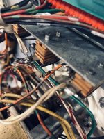
Under the playfield is "interesting"
IMG_7346.JPEG
IMG_7348.JPEG
IMG_7349.JPEG
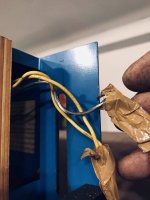
There is this extra part - It is a motor with some cams on it with switches on it. It has been wired into the existing wiring, so I started to investigate what the heck it was trying to do:

Firstly the motor is powered off the rectifier board - two wires soldered onto the bottom of the rectifier board !!! FFS

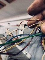
The wires that control the switches (4 of them) :
The first 2 uses the wires from the right slingshot switch (they have been disconnected from the slingshot!
The Second switch is wired into the outhole switch wires.

The wires to the right slingshot coil have been disconnected from the coil and instead run via additional wires to the outhole coil !!!!! The existing outhole coil wires have been disconnected.

So, it looks like this hack is possibly either to turn the game into a timed game, and/or maybe the solenoid driver board has failed so the outhole coil was not firing, so they have 'diverted' the right slingshol coil circuitry instead?
Here are these hacks:
IMG_7350.JPEG
wires off the slingshot coil and extended to go off to the outhole coil

IMG_7351.JPEG
Slingshot switch wires taken off the switch and diverted elsewhere.

IMG_7356.JPEG
Outhole coil has been disconnected and reconnected to the slingshot circuit effectively!

Other issues:
IMG_7355.JPEG
Diodes been cut on many of the other switches - so they wont work

IMG_7347.JPEG
Wire cut on the power board. Why?

IMG_7357.JPEG
The diverter gate has been made inoperable - there is a missing link between the gate assembly and the plunger assembly - not in the bottom of the cab unfortunately

IMG_7358.JPEG
The open and close gate coils have been disconnected.

There is an extra earth wire running from the earth connection on the power supply board up to a lamp circuit on the playfield??

The backbox wiring has been totally removed, including to all the score displays, looks to be all there, so first jobs are to reconnect up all the wirin, the set about removing the hacks and putting the wiring back to how it should be.

Then Test the PSU and make sure it is ok.

This is a two part project:
1. Get the game working as it should
2. Do all the cosmetic work needed
 

Attachments

  • IMG_7352.JPEG
    IMG_7352.JPEG
    79.1 KB · Views: 7
  • IMG_7353.JPEG
    IMG_7353.JPEG
    66.3 KB · Views: 7
  • IMG_7354.JPEG
    IMG_7354.JPEG
    109.1 KB · Views: 7
At least there is s couple of goldball owners on here that you can ask them questions if needed..! :D
 
I saw that on ebay,perhaps like you said they did that hack due to board failure,Goldball uses the combined solenoid driver/lamp board that's a lot rarer than the bog standard ones
 
Gold Ball was my first machine and still here so nice to see another :clap: Mine was hacked too but not as bad, it had an additional redundant transformer added in series to the working original. Was a good machine to learn on, the 2-phase feature lights from the combi card is unusual, as is the less used centre tap transformer. There should be 2x Aux Triac boards inside bb door wired to 2x Triacs on the power supply mounting.

For ROMs I recommend the Oliver/Inkochito home version which incorporates the field kit up upgrade and has an improved attract light show (plus support for 7 digit scoring for your other project!). Your machine looks like it has the field kit replacement plastics.

Let me know if you need any photos, Nedrueds shop log on here is a gold mine of good photos and information.

I'd appreciate good photos of any instruction cards you got with it, am seeking the version included with the field kit.

Good luck with the project:thumbs:
 
Yes I noticed you had one @astyy - nice to know there is another out there. I'll take a pic of the instruction card - it's on the apron

Today I'm tackling all the wiring hacks and getting it back to normal. Power transformer checks out ok, and so does the rectifier board - all voltages present and correct.

Hopefully later I can plug in my alltek mpu board and see what happens!
 
Hi Paul thanks, I've put in my alltek board temporarily, so ok for now.
This reminds me of something to look out for. The other Gold Ball at Pinfest was running an Alltek MPU and one of the gold ball trough gate functions didn't work (when it had previously with original Bally MPU). I thought nothing of it but then somebody on Pinside reported the very same behaviour with an Alltek.

here you go @astyy
Thank you Alan. The last digits of the card part number are obscured, but I think it's original card M051-00371-A032, the elusive Field Service kit instruction cards are suffixed -A031, -A033 and -A035 should any be lurking underneath!
 
So today I've made progress, all the ****ty wiring hacks removed and everything wired back up as it should be.

Put in an altek mpu board as the eisting cpu board needs repairs and new roms.

Machine booted. Some GI lamps and some feature lamps lit. Start button works, a game starts but no solenoids at all.

Can't be that all the power transistors are blown, so I started to look at the board and how it works. There are 3 chips, CD3081 X 2 (one socketed) and a 74LS138 (socketed)

I had a spare CD3081 - so put it in place of the socketed one. Power on - immediately locked on the knocker - so a bit of progress. Also noticed it was also locking on the flipper relay - so the flippers are working even before a game starts.

Ive ordered new chips and some power SCR's. Hopefully that will sort this.

Until I get this sorted I can't really move on with the first phase of this project. Might do some cosmetics instead - playfield needs a good clean!
 
Spent all day - a really long frustrating day on this POS. Remind me never to buy a project with an unobtanium Combined Solenoid Driver and Lamp Driver board - it has been driving me mad.

Eventually today I received the parts to replace the logic circuits for the soleniods - CA3081's X 2 and the LS138 - installed ic sockets on the 3081 tht was soldred in, replaced the other two. Did a dry run with the solenoid connectors disconnected, ran my logic probe over and seemed ok. Tried a real test with the solenoids plugged in - and blew a few drive transistors! One was a shorted burnt out coil, the others are beyond me. Changed diodes on the coils, tested coil resistance - all ok, tried again - all ok - for a while then some other power transistors blew and different coils locked on. Rinse......repeat......same thing this time two different coils / transistors.

Really really odd. So - I went back to dry testing the circuits.new power drivers, changed diode / resistors on the driver circuit. Logic circuits all testing ok.

After hours and hours of messing about, and emptied my stock of transistors, finally realised this was caused by, I think!, faulty connector. The 5V was not getting to the logic circuit properly - so fixed that, and also re-flow soldered the connectors. Once I'd done those things (yep I know - do them first next time) - things settled down. Even got some feature lamps looking like they were working properly.

Now need to wait for some 6045 NPN's or TIP102's

I'm pretty confident now that I can fix the Combo board, and so I'll press on with other stuff -
replacing wrong / burnt out coils
outhole kicker seems very weak in solenoid test - check it out.
replacing blown lamps - check to see if any lamp driver issues?
Outhole switch not working, plus a few other not working.
Gold ball outhole switch trigger wire has been ripped out and twisted, and then the switch has been electrically bypasssed - needs sorting.
 
gotta golden up the gold ball. gold shooter spring and outer shooter spring. and of course the special hidden “gold ball”
545d2e94d5a160e32c935a61f5073cfb.jpg


Sent from my iPhone using Tapatalk
 
no progress on this since before xmas. due to illness. I’ve now received a ton of spare parts so should be back on this asap. The combo driver board still needs a load of repair work, at least three power transistors are blown, so is a resistor and diode. I’ve also got replacement ics that I tested as suspect ages ago. Hopefully I can get all this sorted in the next week.
 
replaced the power transistors and supporting components. it works for a bit then they blow again. replaced 3 again. and after a while they blow. checked all the components, the board, the wiring. the coils are ok correct ohms. the coil diodes all ok and have anyway now been snipped and replaced.
getting frustrated to hell with this now.
 
Last edited:
ps also checked the power supply. all ok 43v dc as you’d expect. i’ve chased the coil wiring down. no shorts all as it should be. also the earth wiring to the driver board all ok

the transistors are correct replacements 2N6045G.
 
Gold Ball was my first machine and still here so nice to see another :clap: Mine was hacked too but not as bad, it had an additional redundant transformer added in series to the working original. Was a good machine to learn on, the 2-phase feature lights from the combi card is unusual, as is the less used centre tap transformer. There should be 2x Aux Triac boards inside bb door wired to 2x Triacs on the power supply mounting.

For ROMs I recommend the Oliver/Inkochito home version which incorporates the field kit up upgrade and has an improved attract light show (plus support for 7 digit scoring for your other project!). Your machine looks like it has the field kit replacement plastics.

Let me know if you need any photos, Nedrueds shop log on here is a gold mine of good photos and information.

I'd appreciate good photos of any instruction cards you got with it, am seeking the version included with the field kit.

Good luck with the project:thumbs:
I’m having a rest from the power transistors issue, so now looking at the feature lights. loads are out. can’t figure out how the two phase thing works yet? can you shed any light on it please @astyy ? I can see the a and b feature lights power feed from the rectifier board from that 20v centre tap, but how’s that enabling the control of two lamps ???

Edit - Sorted - it's pretty cool how that work to control 2 lamps per scr! Someone at bally was a bit of a genius!
 
Last edited:
Looks like I've got some blown scr's on the combi lamp / soleniod driver board. So that's another repair to do to this damned combi board! At least easy enough to do!


Some of the lamp holder sockets are corroded, so not making contact - I'll give those a clean up.


Whilst I've been working on the lamps I've been thinking more about the power transistor constant blowing issue. I'm clutching at straws now, but maybe the batch of 2N6045G darlington transistors I recently purchased are duff? I'll swap the blown ones out for TIP102's which are a similar spec 8A 100V NPN.

Plenty of stuff to do tomorrow!
 
I'm clutching at straws now, but maybe the batch of 2N6045G darlington transistors I recently purchased are duff?

Not unknown.

I'll swap the blown ones out for TIP102's which are a similar spec 8A 100V NPN.

Good idea. If they don't do the trick then see about replacing the solenoids as they could be shorting once they've heated up. I guess you could put it in solenoid test, leave it constantly running and see if it dies on a particular solenoid.
 
Back
Top Bottom