Little bit of progress.
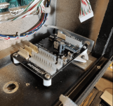
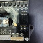
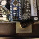
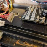
I've measured the environment in that section of the backbox and mapped it, so we can accurately see whats going on.
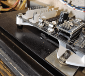
We want to use the existing bolts on right (****ty modelling on that but you get the picture)
We want the bolt for wingnut available on the left
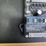
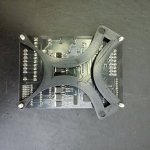
We want this to be cuttable via a laser as well as 3d printed (so have included stand off spacer that insert separately, but can be 3d printed) I have used board height at 3mm so we can use 3mm acrylic (standard size, like protectors)
Kept design style fluid so it looks a little nicer (subjective) I'll likely take a cut out of the middle to save on 3d print time and materials.
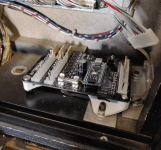
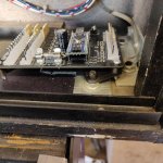
Made better use of the space on the right (moved assembly further right). The board just fits between the bolts, but not between the nuts, so we can move it right, but need to lift it above the nuts when it sits on the frame. Done.
If the user doesnt want to use the nuts on the right to hold it down (would likely be over kill!), you could place the PCB Holder on the same bolts, on TOP of the existing nuts, then fix it down with second nuts. In this sceanrio, user can increase the height of the stand offs between backbox floor and the frame (can probably use the ones we likely all have lying around for pinballs.)
View attachment 129701
The frame sits under the nuts on the right, stand offs press through the frame on the left to support that side of the board
Rough animation to try and show it all below.
View attachment 129703
View attachment 129704
")


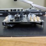
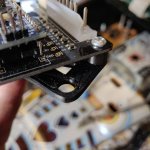


 Of we laser with 3mm acrylic, it will hold that up in the air anyway!