What's new
Pinball info

Register a free account today to become a member! Once signed in, you'll be able to participate on this site by adding your own topics and posts, as well as connect with other members through your own private inbox!

Afterglow 1.3 Board

biglouieuk

Site Supporter
Joined
Dec 22, 2019
Messages
565
Location
Kent
Alias
robllewellynuk
evening all.

Picked up an Afterglow board from a forum member, just installed, what a wonderful thing!

First thing, I am trying to connect via USB to look at config. I get a failed to connect on COM3. Wondered if anyone else had successfully connected or had as link to any troubleshooting?

Second thing was the 18v supply. It would feel better to me if it wasn't pinned to the 18v TP. Anyone successfully run 18v from anywhere else at all? I'm not sure there is 18v anywhere else other than out of the transformer perhaps?

The glow is goooooood. :) Love this little board already...
 
Thinking this might be a driver issue with Arduino Nano, and me not having correct drivers.
 
What config are you trying to look at, the recorded test attract mode (selectable via the dips) or the Arduino code itself? Or are you interested in the debugging output?

Glad you're enjoying it too, they really are as you say, wonderful things. Spread the word!
 
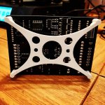
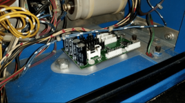
Already spreading the word on Instagram. I printed a little PCB holder for it this afternoon.

IMG_20210107_212116_111.jpg

It's working well in BOP (don't have Helmet plugged in as it's being cleaned up)

I wanted to see what the PC config software looked like for adjusting individual lamps and if I needed latest firmware.

I plug in with usb, have added drivers for ch340 as it wouldn't see anything at all

With ch340 I get flashing red LEDs on the Nano. But the config software says can't connect on com4. I expect this is my lack of current Arduino skills!

Such a cool device...
 
Ah yes the config tool I always forget about that. Perhaps you are on a different serial (USB) port, not com4. Have you installed the Arduino ide?

@Fifty look someone had the same idea (pcb holder!)
 
Arduino IDE is on there now yup.

Config tool only offers me com4 when I plug it in.

I didnt want to mess too much with the ide and sketch until I'd done a little more reading.

I guess I could get the latest sketch from the GitHub and write it on.

Probably dont need it! Just investigating.. 😀

If you want the PCB "mount" STL files, I've stuck them on thingiverse. 👍
 
Last edited:
@caponian (the creator of the afterglow boards) might be better at explaining what's going on with the config tool.

Definately interested in the board holder, great job and thanks for putting it together.

Let me know if you want any advice or direction re arduino, I'm always keen to get more people building cool things.
 
I think you need to check what Coms port is activated on your PC when plugging in the afterglow then maybe select that on the afterglow software,
 
I think so.

Go to device driver in Windows

Plug in, see which Serial device comes on

Says wrong driver, so update driver to ch340 for Arduino Nano

Lights flash on Nano

COM4 pops up in Config Tool

Select that

Says it can't connect.

I'll keep trying ☺️
 
Already spreading the word on Instagram. I printed a little PCB holder for it this afternoon.

View attachment 129597

It's working well in BOP (don't have Helmet plugged in as it's being cleaned up)

I wanted to see what the PC config software looked like for adjusting individual lamps and if I needed latest firmware.

I plug in with usb, have added drivers for ch340 as it wouldn't see anything at all

With ch340 I get flashing red LEDs on the Nano. But the config software says can't connect on com4. I expect this is my lack of current Arduino skills!

Such a cool device...
Okay, first off this is brilliant. I was just talking to @stumblor about creating a 3D printed stand-off to elevate the AG PCB. Thank you for sharing the .stl! Would you be able to show the orientation of your PCB in the backbox with the 3D print installed? I'm curious as to the placement and how it is secured down.

I haven't connected the USB up to the AG board yet, but planned to do so so that I could use the config tool as well. Following this thread...
 
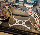
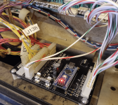
Here you go. One thing to note, I'd like to work on the design a little more. Current design is weak where you screw the board in, if the screws you use are slightly oversized. I have fixed it with supports, but it needs testing, incase the supports get in the way of something on the solder side.


Screenshot 2021-01-08 at 15.26.51.png

In situ, design V1. The board will sit either way on this. Its held on with 2 short screws, these things dont need much holding in place. I am working he design, so that you can have a central "hub" in the centre hole so the board can be dropped over that, twist and lock in place. Getting any screws into anything when its all in place is a mare, needs more design thought.


Screenshot 2021-01-08 at 15.26.41.png

In place so that OUT wires head down into the pinball equivalent of the Great Pit of Carkoon, to the cabinet.

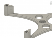
New design with taller supports up the sides to stop the top splitting off.

Screenshot 2021-01-08 at 15.47.06.png
 
I like your design, but I don't like the placement. I haven't installed my AG because the wingbolt gets in the way.

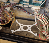
My idea was to design a 3D print that uses the existing bolts in the backbox. See red circles in the image below.

Untitled.png

The 3D print would sit on the backbox bolts, possibly coming through the 3D print so you could nut them down and make things secure.
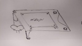
Then the AG board would mount on top of this. The 3D print would 'hover' over the wingbolt so you could still use it. Sort of like this. Excuse the rough sketch, but I think it gets the idea across.

1.jpg 2.jpg
 
Gotcha, good idea! Like it. Maybe slot under those bolts and then lift up.. I'll have a mess about with it tonight for you.. Got no pinballs to play :(.. Line filter dead on Hurricane, BOP in bits, so nowt else to do! There is beer tho...

Is the AG different foot print to the lamp board? Hole placement?
 
Screenshot 2021-01-08 at 22.31.34.png

Right hand side holes will drop over the top of the existing rods, on top of the nuts. You can then put a second nut on top to hold this plate. (Its only 3mm thick)

Board attaches to those 4 holes, with a small washer between board and frame (3d printing isnt good at those vertical "posts" they split when screwed into)

The longer "posts" go underneath the 4 holes, and allow the boards to be screwed into, but mostly they are just stand offs for the far left hand side of the board.

I've also massively over complicated it, obviously.
 
After fitting today, there is a load of fiddling around to fit the frame and the board to it, not much room for screw drivers.

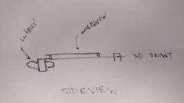
So I was thinking something like this. The centre is a cam, off centre, so it locks when you twist it back square. There would be plenty of force to hold it in place, there is no weight on this thing really, the wires do push it a bit..

I'm more vexed by the 18v on the 18v TP!

 
As an alternative to 3D printing... How about a chat with [mention]Colywobbles [/mention] - about laser cutting that shape.
yup, could defo design it so it can be cut via laser, then add washers and stand offs.. Loads of options. :)
 
View attachment 129681

Right hand side holes will drop over the top of the existing rods, on top of the nuts. You can then put a second nut on top to hold this plate. (Its only 3mm thick)

Board attaches to those 4 holes, with a small washer between board and frame (3d printing isnt good at those vertical "posts" they split when screwed into)

The longer "posts" go underneath the 4 holes, and allow the boards to be screwed into, but mostly they are just stand offs for the far left hand side of the board.

I've also massively over complicated it, obviously.
This is looking great! Yes, dropping over the existing rods on the right side holes is something I hoped would work. If the right side can be nutted down, then the left side really doesn't need to be secured down so solid posts could be used. Essentially they would just be big stand off posts that elevate everything up and allow the owner to still use a wingbolt.

Is there a reason the center is hollowed out like that? Is it just to save on materials?

Here is a screenshot of the LED OCD version to get an idea of what Herg uses for his PCB. He actually incorporates the wingbolt into his design (it's just a regular bolt in the photo) to secure the LED OCD in the backbox. It's hard to see in the image because the material is a grey colour. Attached is his .stl file as well. Maybe this design could be reworked to work with the AFTERGLOW?

Screen Shot 2021-01-08 at 11.00.28 PM.png
ledocd_bkt_mini_r3.jpg
 

Attachments

  • ledocd_mini_rev3_bracket.zip
    148.5 KB · Views: 2
Centre hollowed out to save material and speed up the time it takes to make.

3d printing (additive process) its downside is time to make. With CNC (milling reductive process) it's often quicker. Cutting this out on a laser takes a few seconds! Print will take an hour.

Utilising the head bolt to hold it down is also a great idea. I hadn't thought about that.

It could be the AG board is bigger? There isn't a huge amount of room back there. Let's mock it up and see

I'll grab a few measurements and run a print when I dare go up to the shed. It's cooooold up there!
 
Observation - The above allows for a bolt to be used. It doesnt look like there's enough room to use one of the standard "Wing Nuts" that are often found here.

Just wanted to drop that one in. Still watching in awesomeness :D
 
"As a user I would still like to be able to use my existing headbox securing wingnuts as well as bolts when the board is installed"

Haha

Requirement added. 👍
 
Little bit of progress.

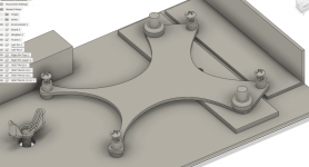
I've measured the environment in that section of the backbox and mapped it, so we can accurately see whats going on.
We want to use the existing bolts on right (****ty modelling on that but you get the picture)
We want the bolt for wingnut available on the left
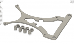
We want this to be cuttable via a laser as well as 3d printed (so have included stand off spacer that insert separately, but can be 3d printed) I have used board height at 3mm so we can use 3mm acrylic (standard size, like protectors)
Kept design style fluid so it looks a little nicer (subjective) I'll likely take a cut out of the middle to save on 3d print time and materials.
Made better use of the space on the right (moved assembly further right). The board just fits between the bolts, but not between the nuts, so we can move it right, but need to lift it above the nuts when it sits on the frame. Done.

If the user doesnt want to use the nuts on the right to hold it down (would likely be over kill!), you could place the PCB Holder on the same bolts, on TOP of the existing nuts, then fix it down with second nuts. In this sceanrio, user can increase the height of the stand offs between backbox floor and the frame (can probably use the ones we likely all have lying around for pinballs.)

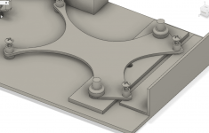
Screenshot 2021-01-09 at 13.20.16.png

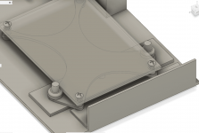
The frame sits under the nuts on the right, stand offs press through the frame on the left to support that side of the board


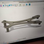
Rough animation to try and show it all below.


Screenshot 2021-01-09 at 13.28.33.png

Screenshot 2021-01-09 at 13.29.57.png
 
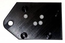
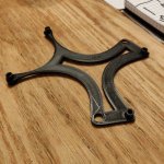
Got a print off. It's ok.. tolerances need a tweak.

It doesn't produce the taller "pins" very well as it prints them round and round.

Pins would be better cut from something else on a CNC (fenoleum is the softer white plastic stuff?) or just make the holes in the frame the right size for pinball stand offs!

Anyway, it got a step closer today.

16102186724312172916945894638766.jpg
 
Happy to give it a go here if that would help??? I should be able to get down to 0.05mm (allegedly) according to Pruslicer... Never gone down THAT fine!!
 
Back
Top Bottom