What's new

In Progress Tecnoplay Space Team Restoration

Zaccaria Keith

Site Supporter
Joined
Apr 20, 2018
Messages
223
Location
Northampton
Alias
Keith Withnall
I purchased this Tecnoplay Space Team about 18 months ago in such poor condition that it wouldn’t have been worth restoring if it wasn’t quite a rare machine. For those who haven’t come across them Tecnoplay was set up by the Zaccaria brothers after the Zaccaria pinball company went out of business in 1987. They produced two games which were basically Zaccaria hardware (Devil King and Scramble) and two that used their own electronics and hardware (X Force and Space Team/Hi Ball. Hi Ball was the same table as Space Team but with a spring mounted cabinet in a vertical console to reduce floorspace. Tecnoplay are still in business making arcade machines today but haven’t produced a pin table since 1988.

The game had a lot of features for the time including 6 players, multiball, ball launch aiming, a high level “toilet bowl” with ball diverter into a crossover ramp, pop-up targets, stereo sound.

I have been unable to find any information on the number of tables made but they don’t appear very often and there are no suppliers of spares for any of the game specific parts including all of the electronics, which makes them a challenge to restore, but I like a challenge!

The playfield didn’t look too bad except that it was missing a vacuum moulded transparent crossover ramp that runs the whole length of the playfield and all of the multiball mechanism both of which would have to be made from scratch.

s-l1600-3.jpg

Things proved quite quickly to be more challenging than I had hoped. I knew the machine had suffered damp and therefore probably rust, but given that much of the cabinet is made of MDF I hadn’t expected woodworm.

1713043857623.png

The front of the cabinet was Weetabix anyway and it transpired that at some point in its history the front of the base had been kicked through to get at the coin box and some wormy old plywood had been screwed over it after which the little bug***s had been very busy.

So off came the front panel:

1713043951364.png

After removing the other bad/loose bits I was just left with these!:

1713043991072.png

So they got thoroughly dosed with worm killer (although I don’t think the worm was still active), treated with wood hardener and then epoxy wood filler where necessary.

1713044029356.png

Lots of expensive birch ply and black faced MDF was sourced from mdfdirect.co.uk and many happy hours with the router using the old parts as a pattern resulted in the following:

1713044081147.png

Lots of Titebond Ultimate and sash cramps later:

1713044116326.png

By this point I had discovered the worm and rot issues in the back box, so another expensive order was placed with mdfdirect.co.uk and even more routing and gluing later:

1713044161654.png

Much of the cabinet bracketry was very rusty and was recovered using electrolytic derusting, which partially reverses the rusting process and leaves sound parts for painting or plating without damaging any plating that might still be present. My rather basic electrolytic derusting setup:

1713044230630.png
Note that the red wire is actually negative and the black wire positive for derusting as the rig was originally made for chrome plating which is the opposite polarity.

Before and after derusting:

1713044335757.png

Coin return cups before treatment:

1713044365876.png

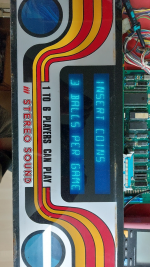
Front of cabinet after applying newly printed graphics and refitting cleaned up hardware (apologies for the reflections from the high gloss black finish):
1713044395485.png

Inside view including restored coin returns, etc:
1713044422649.png

Backbox after refitting restored hardware and newly sourced speaker grilles:
1713044459087.png

In parallel with this I was attending to the electronics boards. There is one main board with the power supply and all digital electronics on it. A display board with the two line vacuum fluorescent display is mounted off this. There is a separate sound board and two small interface boards with the solenoid switching transistors which were intended to be easy, low cost replacements.

Main board and display board:
1713044498584.png

Sound board and interface switching boards:
1713044523963.png

Unfortunately the main board had suffered the usual battery leakage and, as always, the battery was positioned immediately above the processor and eproms (why oh why). Note the nice green and furry test pins alongside the processor!:
1713044561118.png

The alkaline battery leakage was neutralised with a mild acid solution and the corrosion deposits removed before ultrasonically cleaning the whole board, washing and drying before beginning the tedious process of identifying a repairing all the damaged tracks on the pcb.

The board after cleaning, repairing and testing. Note the memory capacitor in place of the battery. There are no NVRAM upgrades available for this game although I might make one later:
1713044618137.png

The board working during bench testing:
1713087146497.png

In the next episode I will look at the playfield restoration. If you have any questions I will do my best to answer them.
Keith
 

Attachments

  • 1713044655061.png
    1713044655061.png
    1.3 MB · Views: 53
Last edited:
Part 2.


Onto the playfield which, as seen in the earlier photo, didn’t look bad from the top apart from the missing aerial ramp and multiball mechanism.
However underneath there was a lot of rust and a few more of the dreaded worm holes:
1713094732331.png

So everything was going to have to come off. First the vacuum moulded plastics:
1713094766785.png

Then the ball guides. The outer one is a single strip of stainless held in place by some folded stainless clips – much better than the usual rusted chrome parts, except that the edges were like razor blades. See if you can spot the blood!:
1713094795995.png

Then it was time to remove the posts. I tried all the usual tricks, tightening them slightly first, applying heat, impact driver, even some Italian swear words, but all but one of the post screws was firmly rusted into the ply and sheared off just below the surface.
1713094847912.png

Turning to the underside it was clear that the lampholders were beyond saving. Note the missing multiball coil and pawl mechanism in the bottom right:
1713094888741.png

With the electronics boards I was lucky as I found a manual for an X Force online which uses the same boards so I had the schematics for the boards. However much searching failed to produce a manual for the Space Team so no schematics for the playfield or cabinet wiring. I even contacted Mauro Zaccaria at Tecnoplay but they have nothing. So whilst the playfield was on the bench I traced out the lamp an contact matrices and the solenoid wiring and made a set of schematics which I will put online shortly. So off came the wiring harness:
1713094973261.png

Leaving just the lampholders:
1713095008984.png

And then there was nothing:
1713095048110.png

So after a good clean, lots of worm treatment and a coat of grey paint it was time to look at the sheared off posts. The number of posts and them being sheared below the surface meant I needed to come up with a new approach.

I found these ball/bead cutting bits like a tiny hole saw. They come in 6 and 8mm diameter.
1713095101043.png

The 6mm was just too small but the 8mm was ideal for coring out the remains of the post and gluing in an 8mm wooden dowel cut in half. A steel guide was drilled to just clear the core drill and clamped to the playfield with a wooden packer below to avoid breakout on the back face:
1713095137199.png

Nice clean hole for the dowel to glue into:
1713095176345.png

Finished dowels glued in:
1713095209452.png

Pilot holes for the new posts:
1713095236047.png

A trip to Andy at PinParts resulted in a large bag of assorted new lampholders which were fitted with new diodes and attached with new ground braid and stainless steel screws:
1713095284148.png

Meanwhile the wiring harness was ultrasonically cleaned, washed and dried before starting to attach it back to the playfield. Note at this stage the contact brackets are still showing signs of rust:
1713095315808.png

With the lampholders rewired the brackets were removed from the contacts, cleaned up in Evaporust and painted. Each contact was cleaned and set and the targets repaired where necessary and then fitted back to the playfield with stainless screws.
1713095383093.png

Each of the mechanisms from the playfield was then stripped, cleaned, inspected and, where necessary, parts repaired or replaced before refitting to the playfield one by one. New coil sleeves, fuseholders and EOS contacts all round. Big thanks to Andy Netherwood who is now used to me turning up with an obscure Italian part and saying "have you got anything that looks like this":
1713095509561.png

Printing new coil wrappers and fitting them improves the appearance significantly:
1713095540079.png
(Clue – the new one is on the left!)

I have since sent the artwork for these to Peter at Inkochnito's as he keeps a great selection of coil wrapper artwork as well as the scorecards and didn’t have these ones. He immediately made a much better job of the artwork than me and will be adding them to his site for anyone who needs them. What a great guy!

Flipping over and refitting cleaned up parts to the top of the playfield:
1713095744606.png

I generally prefer the appearance of traditional incandescent lamps on machines of this era, but normally go down in wattage, e.g. #47 in place of #44 to reduce the load on the transformers. However I fitted warm white LEDs for the GI here as the lamps are such a pig to replace once the plastic bowl is fitted.

The ring of lights around the top of the bowl had several missing lamp covers and broken holders which were unobtainable. However after searching I was able to source some Arcolectric lampholders that take midget flange lamps and fit into the same size hole in the moulding:
1713095780673.png

This and the “Toilet bowl” won’t go back on now until I have made the missing aerial ramp and multiball parts which are the next job. I was fortunate early on to have access to the Hi-Ball that Ross owned and got all the measurements I need for the missing parts.

The big crossover ramp is the trickiest part:
1713095815868.png

It needs to be transparent and this plus its size probably rules out 3D printing. I have looked at making a jig and attempting to vacuum form it like the original but think it is beyond what I could achieve with my facilities and (lack of) skills. I am therefore going to attempt to make it as a stainless habitrail. Not true to the original, although they used a habitrail on X-Force, but potentially more doable and more robust.

I have ordered a load of stainless rod and stainless rings so you will have to wait for the next installment to see if it works!

Questions welcome as always.
Keith
 
I have ordered a load of stainless rod and stainless rings so you will have to wait for the next installment to see if it works!

Keith,
I need to repair wireforms on a STTNG, the welds have come apart above the inlanes.
What’s the welding process you use to make these? I’ve read TIG welding is the way to go.
Cheers, Alan.
 
Keith,
I need to repair wireforms on a STTNG, the welds have come apart above the inlanes.
What’s the welding process you use to make these? I’ve read TIG welding is the way to go.
Cheers, Alan.
I would think TIG would be best, but I don't have a TIG welder so I'm going to try first with a high frequency stick welder and see what happens.
 
Keith,
I need to repair wireforms on a STTNG, the welds have come apart above the inlanes.
What’s the welding process you use to make these? I’ve read TIG welding is the way to go.
Cheers, Alan.
I tried stick welding but even at the lowest arc current of 20amps it was too easy to blow through the 3mm stainless wire - I would expect TIG to be more controllable. I expect the commercial assemblies are cross wire resistance welded but I don't have access to such equipment. Gas brazing was a bit more successful but only after I got some flux intended for stainless steel as the chrome content produces oxides that the regular fluxes won't remove and then it doesn't flow. However the best results so far are using silver soldering with a 440 flux coated silver solder and HT5 flux powder from CuP Alloys. The required temperature can be achieve with a decent butane torch rather than the hotter MAPP gas torch and there is much less discolouration and potential distortion of the wire. Also gives more chance of adjusting things if the alignment isn't right first time. :
1713609993318.jpeg1713610094634.jpeg

I've made a template of the finished wireform that I can use for bending the wires but I'm still wrestling with how to jig the parts for the assembly process. I've made some pieces that can be used to wedge the wires against the rings from the inside either side of the rings, but currently looks like it would need a couple of well trained octopuses (octopi ?) to hold it all together! Suggestions always welcome.
 
However the best results so far are using silver soldering

Picked up some side rails and lockbars I had polished a few days ago and asked the guy if he knew any TIG welders.
Showed a pic of wireforms and he suggested silver soldering which he does, looks like I’m on the right track.
Cheers Kieth, Alan.
 
Part 3 – The wireform and testing

Having decided that silver soldering was the way to go (see part 2) it was time to attempt manufacture of a wireform to replace the missing vacuum formed crossover ramp.

The cheapest source of decent pre-made stainless steel rings I found were some 35mm I.D. by 4mm ones from s3i.co.uk for 66p each. The 3mm stainless rod came from metals4u.co.uk for £4.74 per 2m length.

After some simple tests I decided that 4 wires arranged in a square pattern would work best and have reasonable tolerance for the ball not to jam or fall out on the bends. A pattern was used to mark out the rings and file about a 1mm deep recess on the inside of the rings at the correct location for each wire.

To get started I just clamped two wires at the correct separation and hung the rings off it in the correct position and silver soldered them in place to create this:
20240420_160058.jpg

I could then bend this to fit my template:
20240420_164241.jpg

The kink at the top to stop the ball settling there was made first by clamping the rods between a scrap pop bumper coil bracket and coil plunger in the vice.

I was then able to fold and feed in the outer wires, wedging them in place at each ring in turn before soldering to get this:
20240420_184346.jpg

Following a similar process for the bottom half resulted in this:
20240421_160714.jpg

After soldering on a few mounting points for the multiball switches and centre crossover the assembly was defluxed in citric acid by stealing one of my wife’s plant trays from the greenhouse:
20240422_155548.jpg

It was then positioned on the playfield and locations for the fixings and the ball entry determined and soldered on, before going back into the citric acid.
There was then a tedious few hours spent polishing off the heat marks with the Dremel and small polishing mops to get the finished assembly:
20240426_092806.jpg

Testing in place on the playfield revealed the need for a thin brass shim to cover the join to the plastic scoop and a minor amount of faffing with the top wires to ensure that the ball diverter worked correctly.
A bracket was made to carry the multiball switches and a clear plastic panel fitted to stop the ball dropping through at the crossover before fitting to the playfield.

By this time Wayne J. had kindly 3D printed an actuator cross for the multiball feed (the red cross in the picture) to a design made by Phil D. (many thanks to both) and I had made the other missing parts for the multiball to complete the playfield rebuild:

20240426_182827.jpg

The playfield could then go back into the finished cabinet and start powering up and testing:

20240427_124853.jpg

Inevitably with a machine that has needed this much work there were a few issues that had to be fixed once powered up for the first time, mainly with switch matrix issues due to a bad connector but once they were sorted it proved to be a really fun game with a lot of features that weren’t common back in 1988. The sound is amazing for a game of that age.

After a few hours running it died and wouldn’t boot. :(

The main board went back on the bench and extensive testing revealed a failed logic chip (and also that the Tecnoplay schematic has a lot of errors in it!). I have often found that boards that have not been run for years will exhibit early failures like this so it is important that they get a good soak test. I took the opportunity whilst the board was on the bench to remove the soldered in SRAM chips and fit sockets for some Ramtron FRAM chips I had managed to obtain in the meantime. This meant that the memory capacitor was no longer needed so that was removed and I also increased the size of the filter capacitors on the 12V supplies to improve the sound quality. The whole board then had another refreshing bath in the ultrasonic before refitting:
20240506_171122.jpg

I have ordered some new decals for the sides of the backbox having cleaned up the images taken from the originals before the wormy backbox went to the tip, but still need to find a decent backglass to photo in order to get one made. The only people with artwork at the moment are bgresto in the states and the colours aren’t right on theirs, even if I was prepared to risk shipping a new backglass from there.

It has now had several hundred games played without problem so once the cosmetics are done it should be good to go to Swavesey, and if it behaves there then it will be at Pinfest. :excited

It's been a bit of a marathon, and a lot of a money pit, to restore, but I think it has been worth it as it is such a rare game and actually also a good one to give folks a chance to play.

Questions and comments welcome as always. I will try and post a short video of the game.
 
I've uploaded a video of the gameplay. The right-hand pop-up "space station" has been re-levelled with the playfield surface since I made this as it had settled slightly and was deflecting the ball, but it gives a reasonable impression of the game (and that my playing skills have not improved!)

 
Fantastic work - look forward to seeing it at Swavesey. I do like your games!

I can not believe what you have put into this restoration.

Well done Sir !
It's been one of those where you wonder if you would have started if you knew what would be involved, but I've learnt a few new skills along the way and I'm pleased to have saved it.
 
Very impressive, the new metal ramps look better than the plastic
 
Hi, you did very impressive work.

Looks really awesome

Some weeks ago i bought on an German pinball forum a almost-completely populated Space Team Playfield.

Some parts are missing (Flipper fingers, some posts).

Its very rusty, and i would love to try to get it back working. Its an awesome game

Can you please post the Switch Matrix and the LED Matix? Would be really cool.

I found no information, and i try to use an Lisy80 board with emulation to get it back to life.

Thanks sir.

Greetings Marcel Cevani
 
Last edited:
Hi Marcel,
Good to hear that you are going to try and get another one saved. :)
You can get the schematics for the X-Force here and the boards are the same as the Space Team (although I have found a number of errors in the board schematics that I haven't had time to document yet). Are the boards present in your machine? If the battery damage isn't too severe they should be salvageable and I may be able to help you with that which I will do via a direct conversation to move it off this post. The schematics I have made specifically for Space Team are attached.
Cheers
Keith
 

Attachments

  • ST Top Horseshoe Lamp Schematic.pdf
    12 KB · Views: 5
  • ST Switch Matrix.pdf
    9.1 KB · Views: 2
  • ST Solenoid Schematic.pdf
    39.1 KB · Views: 3
  • ST Power Supply Corrected.pdf
    1.1 MB · Views: 2
  • ST Lamp Matrix.pdf
    8.9 KB · Views: 2
  • ST Flash Lamp Schematic.pdf
    17.1 KB · Views: 2
  • ST Speakers and GI Schematic.pdf
    16 KB · Views: 2
  • ST_SOLENOID_TABLE.pdf
    28.8 KB · Views: 3
Back
Top Bottom