What's new

T2 "CPU String" lamps not working

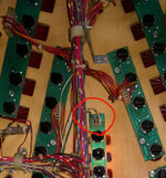
I am going to take the board off again at the weekend and resolder this pin on J115 (I think that's it). Will try and melt the burned solder and reflow it.
The most burnt looking pin on J115 is pin 11, which is not the Green GI circuit serving the CPU light board., so that one is not the issue. The green circuit is pin 5 and pin 10 of J115. Both of these look OK in pic but check for continuity in the circuit (using DMM in diode/continuity buzz test. Pinwiki has an excellent write up on GI operation and diagnosis including a really neat diagram of each of the 5 GI circuits. https://www.pinwiki.com/wiki/index.php?title=Williams_WPC#General_Illumination_Problems

And I wouldn't just carry out random work on a board until confirming exactly what the fault is through testing and would also caution against trying to doing any board work unless you have a temperature controlled solder station, not just an iron.
 
Last edited:
My office is near Metro Centre, so relatively close to you. If you want some hands on help with this and a bit of a tutorial on testing etc., I'm happy to head across after work some time. This stuff is much easier to do in person than online like this. I WFH most times but am next in the office next Wednesday so could arrange something around that. Let me know.
 
My office is near Metro Centre, so relatively close to you. If you want some hands on help with this and a bit of a tutorial on testing etc., I'm happy to head across after work some time. This stuff is much easier to do in person than online like this. I WFH most times but am next in the office next Wednesday so could arrange something around that. Let me know.
I'd appreciate that greatly! I'll DM you.

And on the manual page 1-28, it has the GI tests. They all pass, but the. There's "Lower Right Flipper" and "Lower Left Flipper" and those are not on the test menu, they're also not numbered on the "Sol. no" column.
 
The flipper solenoids of a T2 aren't in any test, because they don't have solid-state 'Fliptronic' control - apart from the relay switching On to complete the ground circuit, it's all down to the player pressing the buttons. The Cpu has no other control of the flipper solenoids, it only sees (or should see) those opto chips show 'switches' in the games' switch matrix array as they sense current flowing.

And in any case, Williams games with Fliptronic (or rather F/Tronic II) don't include them in the regular Solenoid test anyway.
 
Last edited:
And you found them already as per above. These are in parallel with backbox flasher which you activated already in testing. I am sorry to say that the soldering you are showing on your photo is crap - this needs to be redone, somebody already managed to drag a pad off. This means too hot/big an iron.
Measure continuity on the Blk-red/blk-orange cable back to J126-6 and J126-7. They should also be on J125-7/8 for the backbox. You should also have continous power on the lamps via red/white J107-6. The latter is looped from lamp to lamp so may well be interrupted. Measure voltage at lamp socket with pinball on, you should see 20V plus on the lamps.

Sorry, this is referencing @Dinsdale last post. Get a proper solder station (recommend Ersa or Weller) with good electronic, cored solder and a sucker/desoldering braid if you did that soldering. These boards are old and weren't the best quality when they started. It is very easy to delaminate the pads and you'll be suddenly looking for a new board.

I didn't do that soldering, I don't know who did but it probably does need looking at. Noted on the soldering station.

Just an update, the punch down tool came, at £40 it was expensive and unfortunately it just flashed the light when I pushed it in, but wouldn't stay that way when I took it out. I think something is wrong with the crimp connector. Think I need to completely redo it.

Anyway, @Asiapinball has very kindly offered to pop round and take a look at some stuff, and give me an opportunity to explain myself better and for him to show me where I am likely going wrong testing stuff.
 
And you found them already as per above. These are in parallel with backbox flasher which you activated already in testing. I am sorry to say that the soldering you are showing on your photo is crap - this needs to be redone, somebody already managed to drag a pad off. This means too hot/big an iron.
Measure continuity on the Blk-red/blk-orange cable back to J126-6 and J126-7. They should also be on J125-7/8 for the backbox. You should also have continous power on the lamps via red/white J107-6. The latter is looped from lamp to lamp so may well be interrupted. Measure voltage at lamp socket with pinball on, you should see 20V plus on the lamps.

Sorry, this is referencing @Dinsdale last post. Get a proper solder station (recommend Ersa or Weller) with good electronic, cored solder and a sucker/desoldering braid if you did that soldering. These boards are old and weren't the best quality when they started. It is very easy to delaminate the pads and you'll be suddenly looking for a new board.
I have replaced this pin header myself and believe me that this (blank) pad was off due to the previous pins burn not because the iron temperature. Im normally careful with them boards hence you dont have perfectly flowed solder on the photo.
Some cracks could happen when the board was removed but I would check the continuity from the pins to tracks on both sides and not change completely new header and not stress the board more.
 
I've just checked my phone to find some old videos of this (prior sale) and my previous T2. The CPU lights are not part of the GI. They interactive/controlled.
 
Last edited:
Unfortunately, can't really help much as a remote repairs are really not my thing. I can fix everything as long as I can put my hands on it. I would simply chase the CPU leads to the backbox and start from there. Hope that at least the non-GI info helps a bit.
 
Unfortunately, can't really help much as a remote repairs are really not my thing. I can fix everything as long as I can put my hands on it. I would simply chase the CPU leads to the backbox and start from there. Hope that at least the non-GI info helps a bit.
That's why I offered to pop over and help @Dinsdale out on this. 9 times out of 10 this type of thing turns out to be relatively quick and straightforward to fix but sometimes near impossible to diagnose remotely. So looking to a few good games in it once fixed. It looks like a nice machine from the pics.
 
Does the cable in question terminate at the connector or is it looping onward? If the latter, the cable has no break at least. Is the cable lose in the metal slot in the IDC connector? Just held in by the plastic retaining tabs? If the latter, take it out and check, if enough wire strands are broken or cut to keep it from making reliable contact. If it is sitting at the bottom of the metal slot and is tight there after pressing it down though measure continuity from the other end of the cable to the female side of the connector. Look into the connector to see if tabs are bent, broken or corroded.
IDC connectors are pretty reliable in low current applications and as long as the correct tools are used on them. Using a screwdriver can bend the cutting slot open which can cause issues like this.
The CPU lightboard is not connected to the GI header if that's the one you are thinking of, also it has been crimped to molex by the previous owner/operator with Y-spits instead of loops
 
My understanding is that this is one controlled lamp not working due to contact problems at the respective light board, i.e. under playfield. Hope I got this correctly.
 
Obviously there is no-contact somewhere but got nothing to do with the (GI) header pointed by you. Probably another header on the driver board (lightboard was reflowed). Unfortunately without following the cables I'm unable to say which one so hopefully Asiapinball will find out.

I just don't like when people jump into some conclusions without knowing all the details. This can only lead to more damage.
 
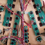
The center CPU lamps ARE PART OF THE G.I. circuit NOT the controlled lamps on the lamp matrix as suggested above, just because they flash on and off does not mean they are controlled lamps the G.I. strings can be turned on and off too.

look at the pictures below and you will notice a number of things that confirm this
1. The g.I. string used on my last T2 is clearly Green and green/white and on all he machines I've had ( 7 to date!) 2 example's below
2. the controlled lamps use red and yellow as the base wire colour, as per all the other lamp conectors in the pictures
3. when the lamps flash the all turn on and off in unison
4. the wire is a much thicker gauge on the G.I. strings
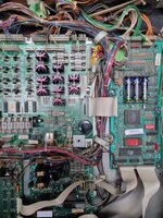
5. look at the last picture and you will see them connected to the G.I. connectors ( J120 and J121)

these 2 connectors can be swapped ( J120 and J121) as they are in parallel to see if its a bad board pin connection/dry solder joint
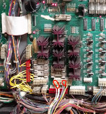
the supply from the transformer can also burn out and cause the same issue SEE PICTURE 3
as i had to replace both plugs and board pin headers to get a solid connection
my advice would be to do exactly the same as picture 3 and then your woes will be over and put to bed im certain from what you have said before
the bad news is you will have to remove the power board to replace the headers and a decent soldering iron to hand and a molex punch to refit the wires into the plugs (unless crimping them, and an even more expensive tool!) its never a bad thing to replace these especially if there are signs of heat and burnt connectors in any case.
hope this clears any doubts about how its wired and what to do next?

IMG_20200417_105027cpu.jpg
IMG_20200421_120155-cpu lamps.jpg
IMG_20200417_140025cpu.jpg
 
@Fishbulb You are right. Bit of a mistake/confusion on my side. Whenever someone says GI it makes me think about those powered by J115. Especialy that few ppl pointed this header out as a possible problem.

Forgot that backbox lights etc can be named GI. I didnt mean matrix lights.

Those two headers were already crimped to molex (not by me) but I'd check if some of the connectors didnt slide out. 20220711_184054.jpg
Early photo of this pin.
 
TBH Chris B. nailed it in the first couple of posts, and J115 has clearly been hacked and has the wrong colour wires in most of the connections they should all be yellow or yellow and white, you will need to check that too, as it could easily be wired incorrectly,

also for belt and braces, re-flow the solder on the pins on the lamp board itself as these too often suffer dry joints and not always obvious.
 
Wires on J115 were extended and Y-splitted by someone hence the different colors but the machine was fine while with me so they should be in the correct order.
Its more likely to do with 121,122 as you said. Im quite sure I've reflowed them too as well as the light board but obviously problem is in that area. Hopefully not one of the transistors obove. Makes me actually curious what's its going to be :)
 
Last edited:
Wow, thanks for all the back and forth on this. It is a great community and I'm even starting to understand more by repetition...

I think @Asiapinball will be able to give some informed facts based on his findings. I hope it's quick, as I'd rather him spend time playing the game and hoping he doesn't beat my high score! (77.5m)!
 
@Asiapinball - what a legend this bloke is.

He's just left, he's helped identify all my issues and even fix some.

One look, the pin looked fine to me, but with his trainer eye he could see a hairline crack all around the join. This explained why the list was flashing when I pushed the wire in, I was just giving it enough to make a connection. Soldered, and sorted.

Kickback not working was a bend in the switch, bent back, all good.

Numerous flashers out looks to be corrosion on the brass inside.

Left flipper switch looks to be a bad Opto. He's going to come back and desolder and socket a new one. What a hero.

Weak flipper is down to the need to tighten or replace flipper plunger which has too much play.

He even explained a credit dot, I had no idea that meant it was referring to an error on the machine. It's these little things.

The continuity tests with the multimeter helped me to no end.

When soldering he showed me about the paste, and technique and best practice. I'll be investing in a new soldering station as well as an imperial nutdriver set.

@Asiapinball - thanks again, with all the excitement I forgot what the problem with the GI CPU lights was! 😂
Gi problem was q16 - will fix that when the board is out to do the optocoupler.
 
Happy to hear that it's all sorted.
At least I was right on the kickback :)
I've replaced both plungers but could be some bad batch with poor quality plastic link (happens).
 
Thanks for all your help Chris (and Jay, and DrHex, and everyone else).

I'll buy a flipper plunger and stuff and replace it, be good to do that anyway for practice!
 
Back
Top Bottom