I didn't mean to appear facetious, but the use of flashbulbs has always been to attract attention; with a couple of System 11 games, the flashbulb routine for a High Score entry has to be seen to be believed.
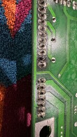
There was a burn at the back of the board when I took it off on J115 when I was looking at a different issue but seller said it wasn't an issue as it wasn't used.
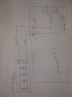
I think that's mistaken - it's a 12-pin connector, the intentionally blank 'key' pin and a 'Ground Reference' leave 10, enough for 5 2-wire ac input circuits, so what isn't used?. As I read the schematic, 'Green' string sends power out to the playfield lamps (all four of them) from pins 5 and 10 of the connector pictured. It receives its input from J 115, with pin 5 supplying Fuse 107, and pin
12 returning power from the control triac, Q
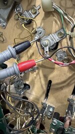
12. Either of those points not actually making contact would knock out Green string. The connecting pins themselves may show an ac reading, but if a pin isn't in contact with its copper trace on the circuit board it's no good. I'd measure continuity, from a) J 115, pin 5 to F 107, and b) J 115, pin
12 to Q
12 (I'm not sure which actual terminal of it, though).
Correction; the circuit return is as Asia says below, from Q 16, which connects to pin 10 of J 115. Disregarding Ground and Key, pins 2 through 6 each connect to a fuse, while 7, 8, 10, 11 & 12 connect to a triac.
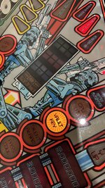
As to the flashbulbs, it seems the drive transistors for them, Q 38 for left and Q 40 for right, are working, and each supplying the lamp on the Insert Board. They have two separate connectors, J 126 for the playfield lamps and the smaller J 125 for the back box lamps, connected largely in parallel on the circuit board. Each of these uses pin 2 for the right side circuit, and pin 3 for the left. So both connectors should have the wires for these lamps in those pins; Right is Black with red trace, Left is Black with orange.
Just to confirm, though, 'testing right and left slingshot' does mean in this case 'left and right slingshot
flashbulb'?. The slingshot coil drives shouldn't have a flashbulb piggy-backing onto them. In play, the lamps may accompany the coil operating, but not from the same driver circuit.
And Sarge, is the mention of 'Hot Dog' flashbulb left over from Funhouse?
No, Funhouse had 'Superdogs'. The playfield drawing suggests that these are the lamps for the 'Autofire' crescent-shaped insert. That chart also seems to have the additional listing of pins in J 125 wrong.


")