Pinball info
You are using an out of date browser. It may not display this or other websites correctly.
You should upgrade or use an alternative browser.
You should upgrade or use an alternative browser.
Revenge from Mars LCD fit and how to make sync adapter
- Thread starter newdos
- Start date
thats almost a reason to do it - that back box was a killer to shift!
- Joined
- Jul 21, 2011
- Messages
- 11,336
- Alias
- Ive
Put an RFM together on my own once. Never again. Almost vomited with the effortthats almost a reason to do it - that back box was a killer to shift!
And me - lifting that full weight head up nearly put my back out... permanently!!Put an RFM together on my own once. Never again. Almost vomited with the effort
yes guys a very good reason to do it alone!
yep remember they are only CGA graphics anyway if I recall correctly
cool!!!Yep, 640 x 240.
- Joined
- Jul 21, 2011
- Messages
- 2,468
With a crt tube, it's the graphics are softened, lcd shows exactly how the graphics are really. It's like vinyl vs cd.
If you find you have to move the head on your own, fit a strap around the back and into the angled front section. This gives you a good secure handle to hold the oversized head with.
If you find you have to move the head on your own, fit a strap around the back and into the angled front section. This gives you a good secure handle to hold the oversized head with.
Hi all,
I have spent hours looking everywhere for the diagrams to make a sync adapter for my RFM so I can fit an LCD screen. I have finally done it and got it working, so thought I would share it here.
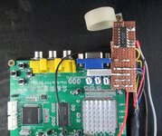
I bought a cheap cga to vga converter off ebay first - shown in the pic. You will then need a vga monitor cable and a 74ls02 chip to convert the H&V sync to a combined sync. I used a Dell 19" LCD computer monitor I had lying around.
First job cut off one end of the VGA cable and strip back the wires. You will need to find the red, green, blue, horizontal sync wire(usually grey) and the vertical sync wire(usually white). All the ground wires can be twisted together. sleeve each of the wires with heatshrink.
Next solder the red, green, blue and ground wires to the respective pins on connector P3 on the board.
Now for the 74ls02 chip. You only need pins 1,2,3,7 and 14. Solder the Horiz sync wire(grey) to pin 2 the vert sync wire(white) to pin 3. Pin 1 is the combined sync ouput and a wire from pin 1 goes to the pin marked 'S' on connector P3. Add a wire to pin 7 for ground and a wire to pin 14 for +5v. This power can be got from within the p2k PC case. Don't forget the board also needs +5v power so just tee together the power leads then off to the pc case for your supply
That's it!!! plug in your new lead to the p2k PC monitor socket and put another lead between the vga socket on the adapter (P4) and your monitor and off you go. Mine worked first time so good luck!!!
Will add more to this when I actually fit it into the RFM.
Feel free to ask any questions.
Kev
View attachment 4293 View attachment 4294
what is the chip put into ? , can't really see what you are using to hold it.
- Joined
- Jul 21, 2011
- Messages
- 2,468
I think he's using a floating socket. When I do it, I glue the chip upside down to the blue connector and then solder directly to the pins.
You have a pic of your set up
Do you have a pic of your set up?I think he's using a floating socket. When I do it, I glue the chip upside down to the blue connector and then solder directly to the pins.
Do you have a pic of your set up?Mine came with a little section of varo board (if that's what it's called) soldered onto the pins. Quite a secure solution.
Is the first time I've worked on this machine , and as everyone knows it's not like no other pinball machine with the computer and everything else .
yes mine was just in a floating socket as Andy said
You have a pic of your set up
Not right now, my machine is at work. Can take one soon.
Thanks so much , just can't see the other side and I hope I'm not biting more than I can chew ....lolThis is how it had been done on the machine that I took delivery of last week.
View attachment 15626
Ordered the converter , and a power supply for it and was going to power the lad from the computer on top, if I do it the way . Do I still need the chip, and if so , I have to order that too.
Lad ..... Meant LCD , sorry
yes you still need the chip however you power it
- Joined
- Jul 21, 2011
- Messages
- 2,468
You can pick up 5v supply from the power supply in the computer case. And spare black and red connector.
yep thats exactly what I didYou can pick up 5v supply from the power supply in the computer case. And spare black and red connector.


