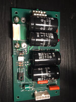
What's new

How do I get the strobe going on my AFM? (now fixed)

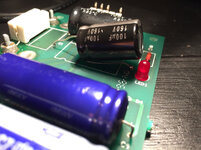
Ok I’ve ordered a thyristor replacement for the 3 legged thing at Q1 (with help) but now to replace the bulging cap. Manual says it’s ‘100/100NP’ which I’m presuming means 100V and 100uF, am I right?

If so, can I use a 160V 100uF that I have instead?

You can.
 
Ok it’s in, wish me luck
uploads.tapatalk_cdn.com_20171102_142fc802025afd38536b6a8dacc27a0a.jpg

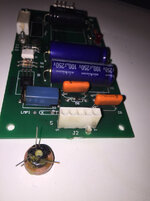
Edit: bollo_cks it didn’t work. Oh well, needed replacing anyway as it was a time bomb. I’ll have to wait for the Q1 thyristor to arrive in a few days time and then try replacing that and try again. Nothing ventured nothing gained and all that.

/shrug
uploads.tapatalk_cdn.com_20171102_f216ee2370b70c3503e71e7ad3a68bc7.jpg
 
Last edited:
Hi Dan as long as the voltage rating is the same or more than the one you are replacing you are fine, as long as it fits and I would say it is 100 uf as it’s an electrolytic and they are usually uf (not nano/pico farads)
WHOOOOOA there.
I think the fact that Dan hasn't posted his distress at the board exploding is evidence that the fault is BEFORE those capacitors in the circuit.

Those are 100uf, 100V non-polar (NP) capacitors.

Standard capacitors are going to go pop.

I should have looked closer before I called it a 'normal' capacitor in my previous post, to be fair. But yeah, that NP in the code means something.
 
Yup NP is non polarised. You need to replace like for like on that one :)
 
Ok so ..... any idea why is power not getting there, and can you link me to what I need to buy from eBay to re-replace that cap please?

I have no idea what a nonpolar cap is except that probably it has nonpolar bears on it.
 
[QUOTE="Monkeyboypaul, post: 229629]Pinbits sell a ‘better’ strobe bulb, and the white cable, plus Homepin do a ‘better’ strobe board.[/QUOTE]
maybe I should get this cable and the Homepin board if Q1 replacement doesn’t fix it (along with new cap)
 
It looks like the Homepin fellow has been scathingly critical of the original board design: https://www.aussiearcade.com/showth...ttack-From-Mars)-STROBE-board-PROJECT-STARTED

With those criticisms and your lack of success despite all the replacements, it looks like these boards are right bastards.

Just for sanity's sake, there's definitely 50V AC, and +12V DC coming from the power driver board in the backbox to the strobe PCB, right? J1 pins. Check those with the strobe board disconnected and check on the cable that connects to the board, just to rule out any issues earlier in the pathway including cable. Checking the cable is a lot safer than trying to test any point on the board, as the other guys said, death voltages in this circuit but the cable is just spitting out 50VAC, which is marginally safer.

Now, assuming the board is getting power... I'm a bit **** at circuit designs, but in my worthless opinion looking at the schematic, Q1 being dead definitely accounts for the board working - but C1 not exploding when fed a polar resistor seems to be luck as it it's still exposed to alternating current without Q1.

As for a replacement for that capacitor - there is a like-for-like on ebay, it's ridiculously priced for one capacitor of this type IMO but the only place I've found to get this sort of thing cheaper is to go to the wholesale electronics guys, like mouser, farnell etc and the delivery charge they will apply makes it more expensive than this, it's only economical from those places if you do a big order - https://www.ebay.co.uk/itm/CEB-100-...802602?hash=item1a387c092a:g:riMAAOSwc6pZ8Htl

The other option is to take two classic polarized capacitors (like the ones you used) and solder them in series, in same poles to each other. Negative-to-negative or positive-to-positive, it doesn't matter to the circuit which you do. It's theoretically absolutely sound but it will probably feel really dicey and you'll have to get creative in where you stick the buggers on the board. https://electronics.stackexchange.c...tic-capacitor-out-of-two-regular-electrolytic If you do this I recommend heeding Mike (Homepin)'s advice and using 160V caps for the job instead of original 100V
 
Last edited:
Thank you again. Tomorrow I’ll confirm power input then I’ll try that dicey cap trick, will pm you for details.
 
When you do check between pins 3 and 5 for 50V AC, and between pins 1 and 2 for +12V DC (this will only be there when the game wants the strobe to flash)

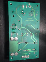
EDIT: Having seen the board in detail and from underneath... William's primary circuit designer definitely had a drink that day and hit 'auto-complete' on the pathing software. I'm a neophyte circuit designer but even I can see that this is absolute shee-ite
 
Last edited:
Um, yeah, I did more reading on that method of creating a bipolar capacitor with two polarised capacitors, and I've gotten cold feet about recommending it to you. You would need 200uf 160V capacitors to make it work (capacitance is dropped by half with this method) and I'm not sure the side effects on ESR are going to be tolerable, knowing that the jokers at Williams already expose this circuit to beyond-specification load. I would give it a go if it were my own board but I feel like after a second correction telling you what to do with this capacitor, it would be ridiculous of me to suggest that and expect trust. The safest option is paying the money for the proper part on eBay.
 
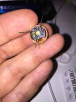
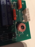
Ok I bought the proper parts for C1 and Q1 replacement. I also wanna replace T1, can someone recommend a source for this thyristor trigger thing? I tried the maplin one you recommended but legs too short and marking very sketchy so I’m not even 100% that it’s soldered in correctly, even though that’s the only way it would possibly seem to stretch.

uploads.tapatalk_cdn.com_20171103_ddb43e8cc3c864e247a36fd38f7b263d.jpguploads.tapatalk_cdn.com_20171103_5ae962e5e7178792657cba5d72dd55f9.jpguploads.tapatalk_cdn.com_20171103_90eeac5eed2cbc0e86a73f3ba8c0e999.jpg

****ing pinballs are are ****s.
/insert gif of pin being chucked off roof
 
Though the first part is functionally fine albeit not suited to the circuit layout, I think we're going with a trigger in the original form factor.

By our powers combined, we're probably not Captain, but the very least First Mate Pinball. We'll soon be flashing balls everywhere, just you wait and see 'em.
 
I’ve ordered some new different triggers with the proper shape, and the original spec large cap, so will soon have replaced C1, U1 aNd T1.
 
Yep. It even has an epilepsy warning sign on it, presumably after some fitting incidents prompted it
 
Nice one. The magic bullet would have been T1, but having pored over the schematic, everything else REALLY needed the help.
 
Can I get any info on where to order these repair parts and what exactly to order? I have a strobe out and want to do a repair on the board and maybe order and new bulb if possible too.
 
Back
Top Bottom