What's new
Pinball info

Register a free account today to become a member! Once signed in, you'll be able to participate on this site by adding your own topics and posts, as well as connect with other members through your own private inbox!

How do I get the strobe going on my AFM? (now fixed)

cooldan

i like pizza
Joined
Jul 21, 2011
Messages
6,456
Location
Ealing, London
Just home yesterday after a long time out on loan, so I’m sprucing her up:
Replaced lock with keyless one
Replaced trim
Replaced rubbers
Installed trough sleeve
Installed 50mm Teflon gliders on feet
Gonna desolder a chip on cpu to install NVRAM

Last job is the strobe not working. What do I need to check or replace, is it a bulb, a board, a chip, or what?
 
Any possibility of anything else I should check first, in case that’s not it? Like voltage at the bulb, or at the board?
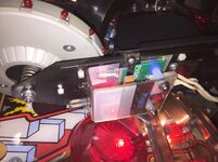
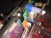
Is it the board mounted under the mothership or is there anywhere else associated with it?
 
Any possibility of anything else I should check first, in case that’s not it? Like voltage at the bulb, or at the board?
Is it the board mounted under the mothership or is there anywhere else associated with it?
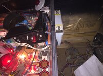
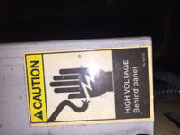
Mounted behind the playfield’s back wall thing, inside a metal casing. Note - contains death voltages.

Less hasty EDIT: the thing under the mothership is just the strobe bulb mounting board - there’s a white triple cable that runs back through the back wall thing into the strobe board metal casing.

Pinbits sell a ‘better’ strobe bulb, and the white cable, plus Homepin do a ‘better’ strobe board.
 
Last edited:
I’ll wait for the links from Spadge I think ...... don’t suppose anyone has one for sale in the uk? Original or upgrade I don’t mind.
 
Ok I installed the new replacement board/strobe bulb from the pinbits link but I still have no working strobe. So what’s next please?

uploads.tapatalk_cdn.com_20171027_12dc7b65a6787059d1b72a5fe5d9a3c9.jpguploads.tapatalk_cdn.com_20171027_4ed8dd3194d7780cec2b2ce7f2f5b3d9.jpguploads.tapatalk_cdn.com_20171027_ea8aebd313225b868d0097cf2838c05b.jpguploads.tapatalk_cdn.com_20171027_add4f8cacad7674a5c2dcb0205c52c73.jpguploads.tapatalk_cdn.com_20171027_4d87e71cb001fe430c8b13bdd1aa8997.jpguploads.tapatalk_cdn.com_20171027_925cbdd09f5e3a27828a816243478120.jpg

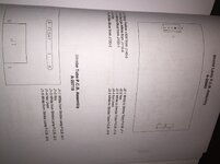
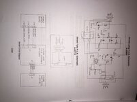
As you can see there’s just a single 5-pin connector from the dedicated small transformer. The pages from the manual may not be relevant as it’s a replacement, but please what should I check? And do I test it in attract mode, in test mode, or in play mode with strobe activated?

If you don’t hear from me then it’s because I’m electrocuted to death.
 
According to the manual I should have 12V DC and 50V AC at the strobe power board. I have 15V DC which I assume is ok but only 35V AC which i assume is my problem.

If so then where do I go next to chase down the source problem?
 
I've had this problem twice previously - first time it was the little transformer T1, second time it was the big orange capacitors. Both in that box of death!
 
Ok I just got talked through testing voltages on backbox and then inside the box of death by Mark Squires, and he’s told me to replace a part called MOC3011 opto coupler so I’ve ordered from eBay.
uploads.tapatalk_cdn.com_20171029_297c19ef673caa690d3ba38ba05f691e.jpg


Before that I beat my high score on the game.

Will report back to close this thread when it arrives and I’ve put it in and tested it out. If no good then I’ll replace the board inside the box of death with the new replacement one from Homepin - but I like to try to fix first before just replacing.
 
Last edited:
The legs on T1 often break but you can’t see easily. A blob of solder in the right place will work if you can get enough contact
 
I'd reflow all connectors, U1 and Q1 first then see about replacing those capacitors.
 
Last edited:
Hi Dan i had a similar issue and as mufcmufc mentions the strobe driver (blue square thing) legs were broken due to vibration presumably i bought a car strobe flasher similar to a maintenance vehicle one from a discount shop and pulled the strobe driver from that. if you need an original lamp let me know i have a spare and i will send you it .
 
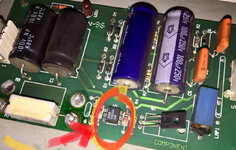
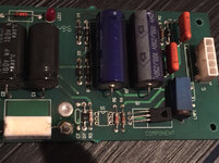
cheers buddy i've now removed the chip at U1, reflowed all connectors and Q1 as suggested, and am waiting for the replacement U1 to arrive so i can solder it in. will report back when job is done (as this thread may help someone in future looking for causes)

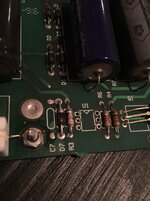
uploads.tapatalk_cdn.com_20171102_009dc8fd91e8a557501cd4e7a58d1332.jpguploads.tapatalk_cdn.com_20171102_1d8c738e4f73b9a2681e009045436014.jpg
 
Last edited:
Optocouplers do go bad, especially with corrosion. If the machine ever had moisture or those caps leaked that'll be it for certain.

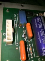
EDIT: Hang on a minute - C1 looks bulged to absolute buggery. It would make U1 failing make sense if the original caps were leak liabilities - C1 looks about to go.
Are you gonna replace that one? You don't need an axial capacitor, just get a normal capacitor and leave one of the legs long, and route it underneath.
 
Last edited:
Soldered in the optocoupler in my octopod, no fix.

So next I’ll try to replace the caps and Q1, right? Oh and Nick mentioned T1 so gonna look for that as well [emoji102]

@mufcmufc Is this T1?uploads.tapatalk_cdn.com_20171102_c067bf3757edbd9082da0505bd8fff99.jpg the blue box thing?
 
Last edited:
Ok I’ve ordered a thyristor replacement for the 3 legged thing at Q1 (with help) but now to replace the bulging cap. Manual says it’s ‘100/100NP’ which I’m presuming means 100V and 100uF, am I right?

If so, can I use a 160V 100uF that I have instead?
 
Ok I’ve ordered a thyristor replacement for the 3 legged thing at Q1 (with help) but now to replace the bulging cap. Manual says it’s ‘100/100NP’ which I’m presuming means 100V and 100uF, am I right?

If so, can I use a 160V 100uF that I have instead?
Hi Dan as long as the voltage rating is the same or more than the one you are replacing you are fine, as long as it fits and I would say it is 100 uf as it’s an electrolytic and they are usually uf (not nano/pico farads)
 
Back
Top Bottom