Pinball info
You are using an out of date browser. It may not display this or other websites correctly.
You should upgrade or use an alternative browser.
You should upgrade or use an alternative browser.
Garbled Data East Display
- Thread starter Carl Spiby
- Start date

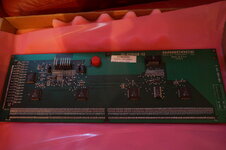
I think I see how these work now. The glass display is mounted on the back of the PCB and there are a f*** of a lot of connections to say the least! To get underneath for the power connector you'd have to unsolder all those pins along the bottom and left edges as shown above. Nasty.
But with the board removed you should be able to easily test continuity between P1-7 and Pin 25 on U1-4, and from P1-8 to Pin 24 on U1-4.
I've just realised that the image above isn't quite the same as what's supposed to be in LW3. Above is GD-032D128-02 whereas the manual says GD-032D128-01.
I still think the most likely culprits are in the ROW section because the display shows lit dots across all columns; it's just they're not vertically in the correct position, i.e., not on the right row. So something in the U5/U8 area, C1-4, C13-17, D1, R173-178 and P1-1, P1-2 and P1-6.
That's my hunch
Before I put the 12vdc jumper you could tell it was trying to display the frames, flashing insert coin etc but since installing the jumper its just static, it doesn't make sense because there must be continuity according to the schematic for the 12vdc on the VDD but its seemingly made it worse.
I've also broken off the 9vac ground wire now from the PSU molex so I need to get a pin removal tool, argh!
I've also broken off the 9vac ground wire now from the PSU molex so I need to get a pin removal tool, argh!
Before I put the 12vdc jumper you could tell it was trying to display the frames, flashing insert coin etc but since installing the jumper its just static, it doesn't make sense because there must be continuity according to the schematic for the 12vdc on the VDD but its seemingly made it worse.
I've also broken off the 9vac ground wire now from the PSU molex so I need to get a pin removal tool, argh!
Bite the bullet and get another display
Not putting any more money into this machine as I'm intending to buy a JM in the not-too-distant future, so it might be coming up for sale if anyone wants a project.
@Carl Spiby, have you seen/read this? Could this be the ultimate "probably just a fuse" fix? 
(http://techniek.flipperwinkel.nl/desega/index3.htm#dots)
(http://techniek.flipperwinkel.nl/desega/index3.htm#dots)
128x16 and 128x32 Dot Matrix Display "Failures".
On Checkpoint to Guns N Roses (all games with small 128x16 and mid-sized 128x32 dot matrix displays), there is a unique problem that can make the game look very broken. Random horizontal lines and garbage can be shown on the dot matrix display (but actually the game's CPU has booted correctly and is working OK). On games with the small 128x16 displays, random horizontal lines can appear first, followed by the entire display lighting and staying lit.
If the backbox 18 volt lamp matrix fuse (8 amp slo-blo, with the blue/white wire connecting to the fuse holder) fails, this can cause the dot matrix display to "crash", causing these problems. Another way to identify this problem is the lack of any playfield CPU controlled lighting. The game will "play" (that is, the game will start and play balls), but with score display problems and no CPU controlled lamps. Simply replacing this the 18 volt lamp matrix fuse (in the backbox) will fix this problem (providing the associated components such as the bridge and capacitor are OK). If there is a lamp matrix power short, or the lamp matrix backbox bridge is bad, the problem will need to be fixed or the fuse will continue to immediately fail.
This problem occurs because the +12 volts needed for the dot matrix display is generated by the 18 volt lamp matrix bridge and the capacitor/fuse bolted inside the backbox (through connector CN5 on the power supply). The 12 volts generated by the power supply board (for the sound board which comes from connector CN6), does not provide this voltage to the dot matrix display! Hence the power supply could be working perfectly, and this problem could still exist.
A Babcock 128x32 display where the 18 volt lamp matrix backbox
fuse has failed. Notice the horizontal "garbage" line across the
bottom center of the display. This problem only seems to affect
the Babcock brand dot matrix displays.

Interestingly, on 128x32 displays, this problem will only occurs on games with "Babcock" brand dot matrix displays. The 128x32 displays made by Cherry and Dale seem unaffected by a failed 18 volt backbox lamp matrix fuse. This happens because the Babcock displays require 12 volts to function, where Cherry and Dale 128x32 displays do not. This problem can also arise on Cherry brand 128x16 dot matrix displays.
This stange problem was solved with the advent of the 192x64 super-sized dot matrix display (Maverick to Batman Forever). An additional backbox 18 volt fuse (F3), bridge and capacitor was added. This backbox voltage supplied power to a switching power supply, implemented on the 192x64 DMD display driver board. This way if the lamp matrix (F2) fuse failed, the dot matrix display remained unaffected.
On Checkpoint to Guns N Roses (all games with small 128x16 and mid-sized 128x32 dot matrix displays), there is a unique problem that can make the game look very broken. Random horizontal lines and garbage can be shown on the dot matrix display (but actually the game's CPU has booted correctly and is working OK). On games with the small 128x16 displays, random horizontal lines can appear first, followed by the entire display lighting and staying lit.
If the backbox 18 volt lamp matrix fuse (8 amp slo-blo, with the blue/white wire connecting to the fuse holder) fails, this can cause the dot matrix display to "crash", causing these problems. Another way to identify this problem is the lack of any playfield CPU controlled lighting. The game will "play" (that is, the game will start and play balls), but with score display problems and no CPU controlled lamps. Simply replacing this the 18 volt lamp matrix fuse (in the backbox) will fix this problem (providing the associated components such as the bridge and capacitor are OK). If there is a lamp matrix power short, or the lamp matrix backbox bridge is bad, the problem will need to be fixed or the fuse will continue to immediately fail.
This problem occurs because the +12 volts needed for the dot matrix display is generated by the 18 volt lamp matrix bridge and the capacitor/fuse bolted inside the backbox (through connector CN5 on the power supply). The 12 volts generated by the power supply board (for the sound board which comes from connector CN6), does not provide this voltage to the dot matrix display! Hence the power supply could be working perfectly, and this problem could still exist.
A Babcock 128x32 display where the 18 volt lamp matrix backbox
fuse has failed. Notice the horizontal "garbage" line across the
bottom center of the display. This problem only seems to affect
the Babcock brand dot matrix displays.

Interestingly, on 128x32 displays, this problem will only occurs on games with "Babcock" brand dot matrix displays. The 128x32 displays made by Cherry and Dale seem unaffected by a failed 18 volt backbox lamp matrix fuse. This happens because the Babcock displays require 12 volts to function, where Cherry and Dale 128x32 displays do not. This problem can also arise on Cherry brand 128x16 dot matrix displays.
This stange problem was solved with the advent of the 192x64 super-sized dot matrix display (Maverick to Batman Forever). An additional backbox 18 volt fuse (F3), bridge and capacitor was added. This backbox voltage supplied power to a switching power supply, implemented on the 192x64 DMD display driver board. This way if the lamp matrix (F2) fuse failed, the dot matrix display remained unaffected.
I wish it were that simple, I checked all the fuses and I had 12v at the connector anyway. I'm going to replace the caps next.
Not putting any more money into this machine as I'm intending to buy a JM in the not-too-distant future, so it might be coming up for sale if anyone wants a project.
Do it. All the time it will save will be worth it.Bite the bullet and get another display
You will sell the machine so much quicker and for more money with a fully working display.
No brainer
I concure
What do good second hand DMD's go for?
Buying a new one is obviously the easiest solution, but theres something to be said for fixing one yourself.
Buying a new one is obviously the easiest solution, but theres something to be said for fixing one yourself.
Sorry, @Carl Spiby. You already said you tried it in another game, an Indy 500, with the same result right? Did you try the I500 display in LW3, just be 100% certain nothing else is at fault in LW3?I wish it were that simple, I checked all the fuses and I had 12v at the connector anyway. I'm going to replace the caps next.
Assuming that the I500 display worked in LW3, then the fault must be on the LW3 Babcock display board. I still think the fault lies in the ROWS section because you've got garbled crap across the entire display. The display is divided into 4 sections vertically, each driven by one of the U1 to U4 chips, so if one of those had gone bad you'd should lose only 1/4 of the display, the remaining 3/4 should still look ok.
If I was closer I'd be more than happy help. If you do buy a new display I'll buy the broken one. I have a mate with a W?D that uses the same display, so I could test it in there.
Your theory makes sense because because C14 has something to do with U5.
I was hoping to use my meter and compare the two displays but its a Cherry in the I500, I haven't tried it in my LW3.
I was hoping to use my meter and compare the two displays but its a Cherry in the I500, I haven't tried it in my LW3.
Ahh... same bit of kit, I understand, just different manufacturers. The schematics for each are in the manual, so I guess the Cherry should work in your LW3, assuming the model number matches?
It should work yes, I will have a fiddle after NERG 
What do good second hand DMD's go for?
Buying a new one is obviously the easiest solution, but theres something to be said for fixing one yourself.
Generally when mucking about "fixing" DMDs, my strike rate has been very poor. I would say 70% of DMDs I've tried to fix have got worse, so I generally now will just stick a new one in.
2nd hand - £50 (ish) with lines out up to £100 (ish) fully working
So I have 30% chance of fixing it then 
So I have 30% chance of fixing it then
Not necessarily, 20% stayed the same and 10% got better
I have a very nice near new DMD I would be willing to let go seeing I have a few spare ones.
£100 takes it.
£100 takes it.
I think I'll go for that Darren, is it a Cherry or Babcock?
Isn't replicas within 'thrash my s2000 range' of you?
He is yes.
Broken DMD, no idea, its had repairs done to it before I got it, the rightmost couple of columns were out before it stopped working, make me an offer, if you're going to Daventry I could bring it with me.
Broken DMD, no idea, its had repairs done to it before I got it, the rightmost couple of columns were out before it stopped working, make me an offer, if you're going to Daventry I could bring it with me.
Will dig it out and let you know.
Just noticed that all the schematics refer to GP-032X128-01 whereas the display I have is a GD-032D128-02, I can't find the schematics for the latter anywhere.
Maybe theres a fundamental difference between the two?
Maybe theres a fundamental difference between the two?
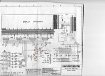
Interesting... hard to find a schematic for the GD-032D128-02! But I did find a scan of a BABCOCK schematic on a French pinball site, http://www.flipjuke.fr, where they seemed to be discussing undocumented differences. Unfortunately, you can't download the high resolution image until you're registered and logged in, and I'm still waiting for my verification email. In the meantime, here's the image:

Notice it has a bunch of other stuff and the author has scribbled some extra components?
I also came across this (http://homepage.ntlworld.com/alienpoker/top/4-TZ-dmd-repair.html):
But before you get too excited the schematic isn't in the TZ manual...

Notice it has a bunch of other stuff and the author has scribbled some extra components?
I also came across this (http://homepage.ntlworld.com/alienpoker/top/4-TZ-dmd-repair.html):
Step Two. I had a closer look at the DMD Display (Babcock GD-032D128),
and one of the surface mount Bypass caps at C9 looked bad (almost certainly was blown).
BTW- Bypass, or decoupling caps are mounted very close to the IC between ground and and its power rails to filter out TTL switching and other "AC noise".
You see one of these below each of the +5v TTL logic chips on a PCB connected between the power and ground pins, usually small as they only need to be rated at 50v. 100nF (which is 0.1mfd) is a common value. Downloading the WPC-89 schematics to get the Babcock display schematic, I confirmed C9 to be .1uF @ 100v.
100v is needed as the column HV supply is +62v or slightly more.
I had a replacement ceramic cap with the right value and so put that in place to get the display going. Disc caps are useful as bypass caps.
I confirmed that now I got the same results with both DMD displays. At least I had something on the display to work from, and the fault was not the DMD “glass” as I had originally thought.
BTW- The Babcock DMD does need to see the +12v correctly from my experience to work, where the Vishay display doesn't use it.
Sometimes seeing “noise bars” on a Babcock DMD will point to a problem in the +12v section. Check ribbon cables first, then suspect the 12v supply isn't reaching pin J604-07
– use a DMM and test for voltage on the pins. If you see something like +5v there, and not the full +12v you may have found the problem.
Check that 12v is reaching the input to the DMD controller, if not you will need to replace :
D8 (1n4742a 12v Zener), D7 (1n4004 Diode 400v 1A), and possibly R7 which is usually 56 ohms and may be cooked.
This wasn't the problem in my case, so my TZ was going to be harder to fix.
But before you get too excited the schematic isn't in the TZ manual...
Is that page 12 from http://arcarc.xmission.com/Pinball/PDF Pinball Misc/Williams WPC-95 Schematics Manual.pdf ?
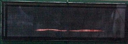
Just so you know, the display looks like a graphic equaliser, the distortion is not a static frame.
Just so you know, the display looks like a graphic equaliser, the distortion is not a static frame.
Last edited:
Ha! It is! Well done  Interesting though that it's different from the LW3 manual but has the same part number. Looking closely at your photo I can see the Q1/Q2 SMD transistors near the P1 connector, so that schematic is right (or at least better) than the -01 version in the original manual.
Still referring to the GP- rather than GD- model though.
Also, the WPC95 schematic doesn't show +12v at all on the babcock? Pin 7 which carries it is N/C
Looks like its derived from +60vdc and a load of resistors? I'll check that bank of resistors tonight out of idle curiosity.
I only read +3vdc at VDD pin which might explain why it partially works.
Also, the WPC95 schematic doesn't show +12v at all on the babcock? Pin 7 which carries it is N/C
Looks like its derived from +60vdc and a load of resistors? I'll check that bank of resistors tonight out of idle curiosity.
I only read +3vdc at VDD pin which might explain why it partially works.
Last edited:
Each of the 8 SMD resistors measure 3.35kohm.


