What's new
Pinball info

Register a free account today to become a member! Once signed in, you'll be able to participate on this site by adding your own topics and posts, as well as connect with other members through your own private inbox!

Garbled Data East Display

Carl Spiby

Registered
Joined
Feb 24, 2013
Messages
2,707
Location
Kendal, Cumbria
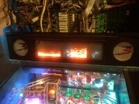
Just popped LW3 on for a quick game to be greeted with a garbled display, I had a look at the repair guide and it refers to a resistor going bad on the smaller style display which produces a similar effect. It is a Babcock display but I don't believe it's related to the common 18 volt lamp backbox fuse problem as CPU controlled lighting is working fine.

Any ideas? Should I just start checking resistor values on the display driver?
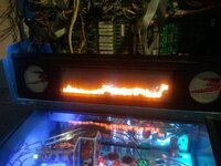
2014-06-30 21.19.51.jpg 2014-06-30 21.20.00.jpg

Voltages at the DMD are as follows:

Black/Grey -107v
Grey/Yellow -86v
Yellow -40v (blocked with a key)
Black 0v
Red 5v
Blue 12v
Purple/Yellow 68v
 
Last edited:
re-seat the flatcables for the display and display driverboard.
Should fix the problem.
 
some bad connection on the display driverboard ?

Try to push on the eproms.

If possible....try it with an other display
 
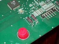
Don't have another display to try, just pulled display ROMs and reseated them with no change but I have noticed C14 on the Babcock leaking, possibly the culprit.

Does anyone know if you can you get to the other side of the pcb to solder a new one in or does the glass obstruct it?
 
That's not gonna be easy.....can't you use the legs from the old capacitor and solder the new one on them ?

My guess is not the capacitor. Can you test your DMD in a friends pinball ?
 
I don't think C14 is the problem....but i would clean the connector.

Better test the dmd somewhere else...if it doesn't work overthere then you can replace C14
 
That just looks like time/ming.

What the machine is saying is 'sell to david for £300.... sell to david for £300'....
 
I assume you've swapped out the actual DMD display itself to verify that it is the DMD and not the DMD driver board has stopped booting?
 
For what it's worth, my old LW3 used to occasionally have DMD complaints and I never found the cause, plus others told me the same.
 
See the green gunk on the negative leg of C14 - that's corrosion of some sort and does need cleaning and possibly C14 replacing. Given thats happened there is there any other green gunk on any other components or connectors..?
 
ok, with the game switched off try reseating both ends of the ribbon cable 6 times each and then see what happens when you switch the game on.
 
Checking the schematic, C14 is across the +5V. The only section requiring +5V is the HCPL-2231 optocoupler (U6). This chip is responsible for providing optical decoupling on the RDATA and RCLK; the ROW DATA and ROW CLOCK signals (see pages 84 and 47 in http://mirror2.ipdb.org/files/1433/Data_East_1992_Lethal_Weapon_3_Manual.pdf).

I'm guessing if C14 has gone bad that might upset the HCPL-2231 which would then provide unreliable clock and row data to U5, the SN75556FM - an "Electroluminescent Column Driver" apparently ;)

It looks a bit iffy. Crusty brown goop, green corrosion on the solder. Even if you push the boat right out and go with a Panasonic capacitor it's only going to set you back 10p!
 
It's only a fiver... and there's loads of junk that you can get from there...
 
What kinda cap is it I've got some 4700uf 35v
Schematic shows its a 10uf 100v.

Seeing as Williams use the same glass, I guess I could swap them over and see if the problem persists.

As for ribbon cables, they have no twists in so can you buy replacements from cpc?
 
Last edited:
Yep, you certainly want to try swapping the glass over.

TBH the garbage in your photo looks exactly like a babcock with mising 12v, but I've seen it a few times on DE where the DMD CPU is not running and it sticks up frozen garbage on the screen. Not seen it like yours though
 
If I read the schematic correctly then, yes, you should have +12V on VDD (Pin 24, Vcc1) and +80V on VPP (Pin 25, Vcc2). These voltages should be across all 4 SN75555FN chips U1-4, so maybe easier to test the power connector P1: P1-7 and P1-8. But I think if you weren't getting good power voltages there you wouldn't get anything on the display...?
 
I appear to have an issue with continuity between P1 pin 7 and VDD, if its cold solder on the P1 connector its right behind the glass :(
 
Yep, no continuity between P1 pin 7 and anything that I should, ****.

Can I put a jumper wire between that pin an the positive side of C13?
 
Last edited:
Glass? Does this circuit board sit directly on the back of a gas discharge display or something?

A jumper would do it if P1-7 really is dry, but it should only be viewed as a diagnostic test and temporary fix. The likelihood is that if that pin is dry then others are sure to follow. Personally, I'd reflow all connector pins but it sounds as though getting to the underside might be tricky? Any chance of a photo so I can see what this thing looks like?
 
Back
Top Bottom