What's new
Pinball info

Register a free account today to become a member! Once signed in, you'll be able to participate on this site by adding your own topics and posts, as well as connect with other members through your own private inbox!

Data East sound issue : +12V issue? - FIXED :)

Had a similar problem with the board from Phantom, opted for a replacement from Sean at Pin Palace.
Easy fix and no more problems.
 
CN6 I already reflowed all pins :(

What's next before I give up and post it to the Legend?
It's possible that reflowing didn't take so I'd do them again.
If that still doesn't solve it, take C4 off the board and check the track underneath it. If the track under C4 is damaged then you'll need a replacement cap for C4. With C4 removed check continunity from DB1 to the top side of C4. Check conitnunity from the top side of C4 to CN6.
 
Keep going Dan (it's an inspirational thread for all electronic wannabe idiots like me;))
 
right, where was i? oh yes,
gif flogging a dead horse (2).gif


It's possible that reflowing didn't take so I'd do them again.
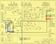
done that, then went one further and removed the CN6 header pins so i could see what went where. i still couldn't establish connectivity between CN6 pin 3 and 6 and the +12V test point though.as a reminder, here's that schematic -

PSU schematic.png


If that still doesn't solve it, take C4 off the board and check the track underneath it. If the track under C4 is damaged then you'll need a replacement cap for C4.
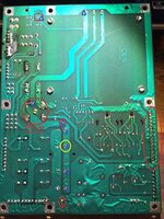
not sure what i was looking for, but there is connectivity between all the points i marked with a blue diamond on the front, and all the points marked with a blue diamond on the back.

PSU from the back.jpg PSU from the front.jpg


With C4 removed check continuity from DB1 to the top side of C4.
yep, they're connected - blue diamonds on back of board.

Check continuity from the top side of C4 to CN6.
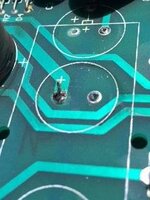
but then i found that there wasn't continuity between the yellow circle on the back and on the front (same point) so all blue diamonds on front and back are NOT connected. yay, a smoking gun! i think i'm getting close - presumably when i removed the 4500uF cap that was there, i killed the through-hole trace. so i fixed it by soldering part of a 0.100 header pin from my spares box

stitch.jpg stitch 2.jpg

now i have connectivity between CN6 pins 3 and 6 and the +12V test point. i just need to solder C4 back in and some new CN6 header pins back in, and give it all a whirl in the machine. i will do that bit tomorrow i think.
 
Sorry, @cooldan, you PM'd me about this but I didn't reply in time. However, much better that you aired your dirty laundry here as it's a great reference for every one else! This is exactly the sort of problem I love fixing. It's just logic. Just test and reduce the number of possible problems.

This was a hard one as the board design relies on one of the four small C4 capacitors to guarantee the through-board connection. Just as you've done C4 can be configured using either 4 smaller capacitor in parallel or 1 big capacitor. It's a good job that when you made the switch from 4 caps to 1 that it totally broke the through-board connection because if a crappy partial connection had remained it would have over-heated and burnt out under load. Soldering in a pin to make a solid connection was exactly the right thing to do.

Don't feel bad, you did well my young Padewan. That is a really, really bad PCB design.
 
Back
Top Bottom