What's new
Pinball info

Register a free account today to become a member! Once signed in, you'll be able to participate on this site by adding your own topics and posts, as well as connect with other members through your own private inbox!

Data East sound issue : +12V issue? - FIXED :)

cooldan

i like pizza
Joined
Jul 21, 2011
Messages
6,456
Location
Ealing, London
Hi fellas.
On my GNR the sound was all flaky, it would come and go. The volume control is by a physical stalk on the metal box inside the door, so by physical hardware rather than by software.

I did some research and got some leads which I worked through one by one:

-I did a factory restore in case the RAM was corrupt.
-I removed and reseated the four sound ROM chips on the sound board, as two of them were giving no sound in test mode.
-I checked and secured the wires attached to all three speakers, which are wired to CN4 on the sound board.
-I replaced all the connectors to the soundboard and a few others that looked crispy on the CPU board.
-I wanted to replace the 20-pin ribbon cable that goes from CN21 on CPU to C1 on the sound board, but don't have one so that will have to wait.
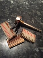
-I replaced that volume stalk 'trimpot' voltage potentiometer which I found was directly connected to CN3 on the sound board.

-Finally I found a smoking gun when I tested the voltages coming from the power supply board. +5V was perfect at 5.06V (4.99 on the CPU board). -12V was ok (I assume) at -13.5V. But the +12V was only 9.3V. Is this my culprit?

http://mirror2.ipdb.org/files/1100/Data_East_1994_Guns_N_Roses_Schematics.pdf

Does page 32/33 (p79/80 in the bottom right corner of the page) of this schematics document tell what and where the problem may lie?
images.tapatalk_cdn.com_15_08_29_84b98d2497ef95583bf81529ab2aa11a.jpg

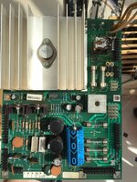
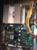
Where physically on the board do the components sit that I need to test/replace? Presumably I am looking for a knackered capacitor or bridge or diode or something?

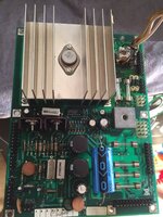
Is it that massive frig-off huge thing top left with a humongous heat sink on it .... or the small grey square bridge to the bottom right of it ..... or one/some/all of the capacitors?
images.tapatalk_cdn.com_15_08_29_4a1978c9ad59070ae0d972c6c9dbe5da.jpg
Cheers guys
 
I'd change the capacitors while your at it they look abit bulgy

(Things with the lil arrow shaped scores on the top)

They can be a cause of iffy sound
 
Hi Dan.......... The smaller grey rectifier is DB1 this sorts the +5v and the+12v supplies for the game if this was fooked I
suspect you would have more logic problems resets etc, than just the sound fault.
 
some info just found

DataEast power supply #520-5047-00 (small
DMD game). DB1 is the square gray metal
"block", right middle of this picture.


For additional reliability on games Laser War to Guns N Roses, it is a good idea to solder an 18 guage wire from the "+" lead of bridge DB1 to the "+" lead of capacitor C4. Solder another 18 gauge wire from the "-" lead of the bridge DB1 (the lead diagonal to the bridge's "+" lead) to the "-" lead of capacitor C1. These added wires will help prevent future problems with cracked solder joints on the power supply board components.
 
Ok thanks John. Anyone else have advice for me after I test that bridge - @pinballmania ? Should I replace any caps? Is that wire supposed to go on the front or the back of the board?

I've not done anything like that before. I've replaced diodes and transistors and a capacitor once but never a bridge and never any off-piste additional jumper wires.

/scared
 
Measure the 12v again but set on an AC scale. You sent to see very low volts. E.g 0.05 or less. If you see significant AC then the smoothing capacitor is ineffective or badly connected. Replace cap and ensure continuity to it.
 
Thanks Andy.

On AC, +5 was zero and -12 was zero but +12 was reading 0.6V

Which cap is the smoothing one that needs replaced, and do you agree with John Oliver's advice above?
 
Last edited:
C4 I think. 18000uf. If there's cracked solder joints the jumpering above may resolve it. But best to replace the capacitor.
 
Andy I thought that the 4 cap @ (C4) boards were for the large DMD games or is the board backwards compatible?

but thinking more isn't C4 filtering the +5v not the 12v Dan's worried about
 
Last edited:
Don't know. But dans pic shows 4 off in that position. My lah also has 4 in parallel.
 
sorry Andy I don't have my D/E m/c any more.... I was going on dan's link to the schematic on IPDB

EDIT ahh just had a look at the pictures of GnR on of the back box on IPDB
I stand corrected
 
I think the boards were designed for either one big cap or 4 separate. Probably cheaper with four radials rather that the one big axial.
 
Um, I'd check your fuse holders that feed the 12v line before doing anything else given the dodgy fuse holder in DE games....
 
Thanks all. Peter I already replaced a bunch of fuse holders but those on the power supply are all good.

I will replace the caps as recommended and report back in case anyone gets the same issue in the future.
 
i continue to plod on with this. i have now replaced the 4 capacitors with one big axial capacitor, and replaced the bridge rectifier. the bridge tested bad, and when the new one was in, it tested good, which was encouraging. but while taking the old bridge out, i did damage some of the through-board tracks so i'm wondering if i need to do anything about that, like remove and try to make a stitch (never done this before but always keen to try new things).

the proof of the pudding is always in the eating - in circuit, the PSU +5V is still 5.06V, the -12V is still good at 13-14V, the +12V is still low at 10.4V (it was 9.3 at the start of all this shenanigans). but more to the point, i now have no sound.

http://mirror2.ipdb.org/files/1100/Data_East_1994_Guns_N_Roses_Schematics.pdf

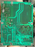
so i tested the input connector to the sound board (CN2 pin 6 is supposed to have +12V) and there was nothing. according to the wire colours, this comes from CN6 pin 6, where also there was nothing. but when i try to understand the schematic (link above) this should be directly connected to the +12V test point ...... looking at those schematics gives me a headache tbh, but i *think* i can see (page 32 of 57 in the link) where this should connect to the bridge and cap i just soldered in. so it's a broken trace, right?

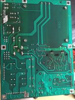
psu front.jpg psu back.jpg

now this power supply board has been previously worked on, and i've already put in new fuse holders, a capacitor and a bridge rectifier. is it worth trying to fix, or should i bite the bullet and get me a new/refurbished DE power supply board, or one of the replacements (rottendog? Xpin board?)

thanks for reading this far. here is a nice distraction by way of thanks - the lovely Alizee
ohmygoodness.gifalizeedancing3.gif
 
that is super generous Andy, thanks. it's more about the education and learning than saving a few quid to be honest, i could just buy a new board but i was brought up to always try to fix rather than replace if possible, and i like to learn stuff. i will have another tinker and then probably take you up on that kind offer.

gif snake in plasticine hat & tache.gif
 
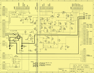
Reading that schematic the +12VDC and -12VDC are unregulated. Highlighting the important parts the circuit here is pretty simple, just the bridge rectifier DB1 and smoothing caps C1 and C4. I've stitched the pages together but there's a bit down the middle missing from the scans:

DE_PSU.png

I would expect to see a little ripple on these as caps C1 and C4 are only providing the most basic smoothing to the half-wave rectification out of DB1.

Checking the rest of the schematic I see on page 3 that the transformer has a centre-tapped winding supplying pins 10, 11 and 12 on PSU connector CN1. This winding is 18VAC or 9VAC on each side. Checking page 6 in that PDF confirms these connections and pinouts on the PSU board.

I'd check the voltages coming out of the transformer itself without connecting it to the PSU. If they're good then check the same voltages are arriving at DB1. With caps C1 and C4 removed check what's coming out of DB1. Pops the caps back in and test again. Also, if you've got DB1, C1 and C4 removed check all the traces and connector pins are making good electrical continuity.

Other than that, all the other stuff on this board isn't doing anything in relation to the +12 and -12 VDC unregulated output unless... there's something odd going on the the +5VDC because that is fed by the +12VDC as well. It would be a simple matter of removing C2 and TR5 to remove this part of the circuit from the equation!
 
Reading that schematic the +12VDC and -12VDC are unregulated. Highlighting the important parts the circuit here is pretty simple, just the bridge rectifier DB1 and smoothing caps C1 and C4. I've stitched the pages together

thanks so much Peter, i returned to this and realised where you'd made bold the relevant parts of the circuitry. so i used my meter and buzzed out connectivity of that entire black lined road map, on the front and back of the board. this is all off-piste for me, i'm a total noob when it comes to anything electronic. i was delighted when i discovered that fuse F2 was bad, and that when i replaced it, this part of the black line also tested good. so i was relieved that i didn't have to try the other stuff you said about the transformer output and removing stuff from the board again .....

Checking the rest of the schematic I see on page 3 that the transformer has a centre-tapped winding supplying pins 10, 11 and 12 on PSU connector CN1. This winding is 18VAC or 9VAC on each side. Checking page 6 in that PDF confirms these connections and pinouts on the PSU board. ....
I'd check the voltages coming out of the transformer itself without connecting it to the PSU. If they're good then check the same voltages are arriving at DB1. With caps C1 and C4 removed check what's coming out of DB1. Pops the caps back in and test again. Also, if you've got DB1, C1 and C4 removed check all the traces and connector pins are making good electrical continuity. .....Other than that, all the other stuff on this board isn't doing anything in relation to the +12 and -12 VDC unregulated output unless... there's something odd going on the the +5VDC because that is fed by the +12VDC as well. It would be a simple matter of removing C2 and TR5 to remove this part of the circuit from the equation!

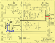
but then at the last minute when i was just about to high five myself (stop sniggering) i re-read my own earlier post and noticed that my silent game was due to no +12V at CN6 pin 6 ..... so i checked continuity of this to the +12 test point, and they're not connected. neither can i see anywhere on front or back of the board where or how they are joined physically. you missed out marking this part on the schematic you kindly stitched and posted -- i have marked it myself in red in the pic

PSU schematic.png

so i think i still have a problem with CN6. pin 2 has continuity with the -12V test point, and pins 3 and 6 are connected to each other, but not to +12V.
i'm determined to try to get to the bottom of this on my own, after all i've come so far already with replacing connectors, a voltage potentiometer, fuse holders, caps, and a bridge rectifier. it's become personal. sorry, i know i'm being pig-headed about this.

so do i focus on CN6 on the PSU, try reflowing or replacing it next? or do i have to do what you said about transformer outputs (more off piste)?
 
You posted an earlier photo of the back of this board and the tracks for CN6 Pins 3 to 6 can't be seen so must be on the top side. If you are getting continuity between 3 and 6 then each pin must be connected to the track and I doubt a reflow will cure. Why not post some close up photos of CN6 from topside.
 
It's hard to tell but I'm guessing CN6 is connected by a track on the top side of the board from DB1 to the positive leg of C4 and on to CN6. The feed to TP3 12v test point is underneath the board also feeding from DB1. If you have +12 at TP3 then you have a problem with the track on the top side of the board.
 
Continuity test CN6 Pin 3 (or 6) to positive leg of C4 and then C4 to DB1. That ought to show where the fault lies. Perhaps a reflowing the solder of C4 will sort it.
 
Back
Top Bottom