What's new
Pinball info

Register a free account today to become a member! Once signed in, you'll be able to participate on this site by adding your own topics and posts, as well as connect with other members through your own private inbox!

Bell Games Saturn 2

ABSOLUTE CONTROL

Registered
Joined
Dec 17, 2013
Messages
153
Location
Worcester, United Kingdom
Well......

I spoke too soon......

Got home last night, Poured a glass of Jack and coke and thought i'd have a quick play on the pin.....

To find out its not working !!!

all the main lamps it up and stayed solid, tried resetting it many times no workie.....
pulled the back glass off and reset it, lamp on mpu flickered and flashed 3 times, Bugger.....

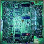
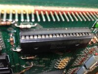
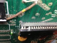
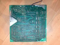
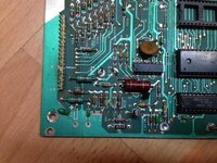
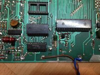
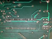
pulled the board out and looked over it, nothing looks fubared, battery corrosion is extremely minimal and all tracks looked good, pulled the f6820p pia's the pins look a bit black and a tad funky and noticed 2 pins chip side soldered ( if thats what you can call it ) but on the back of the board its linked together anyway ?
put them back in, the f6800p is also looking a bit on the crusty side, cleaned it all best i can and put the board back in, turned it on and all i get is a flicker and 1 flash now..... im lost, its my first and im new to them, have spent hours on the net with tuts and videos but i cant see why from working to not with nothing being touched overnight can happen like that.

Any Ideas where i can get a set of chips from and is there any alternative chips like the motarolla mc6820p is all i can find to replace the f6820p ? will it work or not ?

jim
 
Parts came today from andy @ Pinball mania, thanks dude !!!!! awesome, new flipper leaf switches, round targets, balls....shiny balls...... all new sockets and chips, locks, bolts, pop bumper base and much much more.... i did forget rubbers........ where the hell can i get some from like today if not tomorrow.....
 
Well... All chips and holders fitted on the mpu, and got it working finally ..... But some odd things are happening ...... The on board led is constantly lit after the 7 th flash but very dim ......

And for some reason I had game sound with speech a first but after 15-20 mins of playing it has gone to all I can describe as chimes .... Any ideas anyone ?


Sent from my iPhone using Tapatalk
 
ok, sounds all sorted....... just came back without touching a thing......

can anyone please help me im in need to get a diagram or info on the bally 122 - 125 transformer and what output on each pin etc is / should be, as the play lamps are real dim......
and transformer is getting real hot ... I have spent hours searching for diagrams etc but no joy, the other problem i have is the rectifier board is a bell games one not a bally or stern and they are different so i cant test like all the help pages show you..

PLEASE HELP ME .....

jim
 
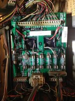
ImageUploadedByTapatalk1388354360.203161.jpg

Bell games rectifier board

What pins / locations do i test on here to see what voltage is where ?

I've been over and over the net and asked a few folk ;) but I'm still Lost.....

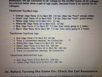
I have tried each lug on the trans to every bit on the board and only came up with a few close ish voltages going by the instructions below

ImageUploadedByTapatalk1388354504.602770.jpg


Sent from my iPhone using Tapatalk
 
Hi Jim,

The 'E' numbers in the pinrepair guide you have for Bally machines and the 'E' numbers you see on the rectifier board in your game don't tie up as Bell changed the numbering.

From digging around the original Bally schematic and looking at the Bell Games wiring info (from ipdb) you should be able to measure the following AC voltages on your Bell board. Have your meter to show AC voltages. Looking at the bottom of the board, where the transformer voltages come in, you can see the points marked with the Bell E numbers.

Put one probe on E10 and the other on E7, doesn't matter which probe where, you should get 240v (mains)
On E3 and E17, 49v
On E2 and E16, 12v
On E4 and E18, 170v
On E5 and E19, 7.8v
On E6 and E11, either 7.8v or 6.9v (schematics contradict each other, but I think 7.8v is more likely)

It goes without saying you need to be careful poking around on there as you have mains voltage flying around. The above list will check out all the voltages that the transformer is pushing to the game. Given that the game will be running under load, you might reasonably expect the numbers above to be a bit lower.

If those check out OK, I'd suspect that maybe those bridge rectifiers might need replacing. Using the Bally repair guide you have and with the machine powered OFF, do the bridge rectifier checks mentioned there.

Good luck
Mark (the F14-cab-decal-guy!)
 
Oh, and meant to say from looking at the Saturn 2 manual that chimes are an option in the sounds if you want them. I suspect something got a little screwy somewhere, keep an eye on it and see if it stays the way you want.
 
Also check the wiring on the transformer, it may be configured for a slightly different mains rating (eg Europe (220v) rather than the UK (240v)).
 
Well just checked all points etc and all bang on except On E6 and E11 thats 6.8v, will that be ok or too low ?
going to go over all the alterations to the bell games convo and see if i can find a back feed or a issue somewhere as this just aint right..

jim
 
6.8 is fine. Did you check the rectifiers? Worth checking the diodes too..

Sent from my GT-I9100 using Tapatalk
 
Cheers mark, tested them still attached and got readings all over the place, will pull them out tomorrow and so another test.

Another stupid question..... On the 'conversion' instructions they say wire the red-blue wire from the PF to pin 4 on door connector now I have looked at this and it's badly joined but it goes to nothing on the plug door side just no pin out but feeds back to the back box don't know where as yet but the wire on the pf goes to the leaf contact on the top small right flipper and so does the green and red wire but that joins to the slam tilt wire on the door connection .... ??? What gives ? Is tat a flipper isolation sort of thing ?


Sent from my iPhone using Tapatalk
 
Found the BR's were open on - to ac on both, amazed to find they were 40A BR's ... so a trip to maplins & £4.60 lighter have a pair of 35A BR's
Both fitted and all PF lamps are bright and look much better. Cheers guys !!! But I still have a problem with 7 random lamps, all dotted all over the place traced all the wires back to the main boards all are fine and continuity is bang on, checked all the. SCR's and all check out fine, did look on Steve kulpa.nets site and found all the scr to pin location info and all these don't run through the lamp driver board so even though they plug into it are they controlled by a chip rather than through the scr's ... It's driving me nuts, I just want it right before I tear it apart and clear coat the PF and get all the metal work perfect etc....


Sent from my iPhone using Tapatalk
 
Dumb question time. The lamps you are having a problem with. .. stuck on or off? If they're off, even dumber question. . Did you check the bulbs? I spent 2 hours before investigating a bulb that was just blown....

Sent from my GT-I9100 using Tapatalk
 
Snux,

all the lamps are always off, and when playing, the target lamps dont light when hit, and the roll over buttons also dont light either ... fod knows .... but i have cleaned all bulb holders and the underside of the optics with cotton bud while i had the bulbs out ( damn they were dirty ) and replaced all the bulbs with new #44's was going to go with 47's but didn't ... All bulb holders and connections checked with a 9v pp3 battery just to check all bulb / holder / wiring was good ( disconnected the looms from the boards first i will add) but other them that I'm stumped


Sent from my iPhone using Tapatalk
 
Can you post a list of the bulbs which are not working? Maybe they have something in common.

Sent from my GT-I9100 using Tapatalk
 
10k on launch ( top of the 3 )
'N' on Saturn on the spinner
Middle 1 on both top lines on combact area ( spelling is correct lol )
Red special on 70k - 140k spinner area
'I' in fire on right hand side targets
3rd up on green accumulator in centre field


Sent from my iPhone using Tapatalk
 
Hi Jim,

It's a pain that the Saturn 2 docs don't list which lamps connect to which lamp driver, but from comparing the Spy Hunter playfield with the Saturn 2 one and making the assumption that Bell didn't change the connections, then I think these are all driven from the regular lamp driver board. What did you read or see that makes you think otherwise (you have the benefit of the machine in front of you, so can probably see something I can't)?

If Bell kept the same connections as Bally for these lamps, then you should find the following details for the lamps you have out. For each I've listed the connector and pin number, then the SCR it connects to. There is nothing I can see specifically in common with these, so I think the chips on the lamp driver are probably OK. I would suspect that something in the chain from the SCR through the connector and down to the lamp socket is screwy.

10k on launch ( top of the 3 )- J1, pin 14. Q9
'N' on Saturn on the spinner - J3, pin 27. Q32
Middle 1 on both top lines on combact area ( spelling is correct lol ) J3, pin 25 and 26. Q36, Q38
Red special on 70k - 140k spinner area - J3 pin 20. Q41
'I' in fire on right hand side targets- J1, pin 12. Q21
3rd up on green accumulator in centre field J1, pin 13. Q20

Given that the pins on the connectors for the lamps in question are close together, I'd first check that the wires are going into the connectors properly. You have on J3 pins 25,26,27 (and 20) not working. On J1 you have pins 12,13,14. Maybe something gave those a tug and they're not sitting properly in the connectors.

From the pinball repair guide, I copied the following. This test will replicate what the SCR does when it's working. It'll provide a connection to ground for the lamps in question. If they do not light with this test, then you problem is somewhere from the connector the the playfield socket. Give this a try for each of the SCRs in the list above and let us know what you get....

  • With the game in display test (ie no lamps on the playfield lit), connect an alligator test lead wire to ground. The bare braided wire in the bottom of the back box works well for this.
  • Touch the other end of the test lead to the ANODE (A) of the SCR in question. On the larger MCR106, the metal face or metal tab is the anode. On the smaller 2N5060 SCRs, it's the lower right leg. To make sure, the pinout for the SCRs is silk screened on the board for a few selected SCR. Look for the lead marked "A".
  • If the lamp does NOT light when the anode is grounded, the problem is NOT on the lamp driver board. Most likely you have a wiring problem, a bad lamp socket, or a bad bulb.

Let us know what you get from testing like this..... If the bulb lights when you do this test then the issue is a little further back up the chain.

Mark
 
The non-lighting bulbs are most likely to be caused by a crappy connector / connector pins with 30 years of crud on them. :rolleyes:
 
I think that nicely summarises what I said! My guess is grounding those scrs won't light the bulbs, so it'll be crud or a loose wire somewhere.

Sent from my GT-I9100 using Tapatalk
 
Just tested before heading to work and ......


10k on launch ( top of the 3 )- J1, pin 14. Q9 is lighting the 50k green lamp 2nd up on accumulator
'N' on Saturn on the spinner - J3, pin 27. Q32 is lighting the middle bottom lamp on combact area
Middle 1 on both top lines on combact area ( spelling is correct lol ) J3, pin 25 and 26. Q36, Q38 Q36 is lighting the x4 green lamp bottom of accumulator, Q38 - nothing and no wire in 26 pin on J3 plug
Red special on 70k - 140k spinner area - J3 pin 20. Q41 lighting middle row right side in combact area
'I' in fire on right hand side targets- J1, pin 12. Q21 nothing and no pin / wire in 12 on J1
3rd up on green accumulator in centre field J1, pin 13. Q20 lighting 6th up green lamp on accumulator

Given that the pins on the connectors for the lamps in question are close together, I'd first check that the wires are going into the connectors properly. You have on J3 pins 25,26,27 (and 20) not working. On J1 you have pins 12,13,14. Maybe something gave those a tug and they're not sitting properly in the connectors.


it does have a extra lamp driver board on the left had side that original loom plugs into, then goes to the LDB so i grounded all the scrs on that and that seams to control the yellow on the accumulator

other then that..........8lbs sledgehammer might sort it....
 
That's a shame, means that Bell didn't keep the original wiring sequence for the lamps after all. I would suggest you work down through all the SCRs on the lamp boards and ground them one at a time, to see which ones control what. If nothing else it'll be a useful reference for anyone else doing this some other day. If you find the SCRs that do light the bad bulbs post here which ones they are, maybe they do have something in common after all. If you find that some of the bulbs still don't light after the ground exercise, then you have a bad connection somewhere between the bulb and the driver board.

I guess you tried the "pull all the connectors off and push them back on again a couple of times" trick? That can clean the connectors enough sometimes to make things wake up. Can you also post a picture of extra lamp board? Maybe if it has a model number or something we can track down a schematic for that, especially if it turns out all the non working lamps are controlled by that board.

Mark
 
push pulled, removed, cleaned, checked all connectors, wires, scr's traces etc,.... all i can think of is there is either a real bad wiring issue from factory or 'someone' has been into it and played around with it,
i do have pins in J2 that have been left in the plug but no wire going to them 3 or 4 if i remember right. and cannot find any 'loose ' wires,
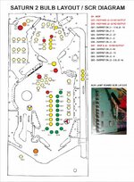
image of aux lamp board is the same as
http://stevekulpa.net/pinball/as-2518-43.jpg
but original brown J2 plug goes into the 15 pin and there is a hard wired loom / black plug that goes into the J2 on the LDB, the bigger pin ( 20 ) has 2 white plugs that go direct to the PF.
will rip it apart again tonight and see what i can find
 
You've got to remember this didn't come from a factory - it was a kit that individuals used on their (knackered) donor game so they could have been bodged right from the start.

You really need to replace the connectors on J1 and J3 before going any further and you check all the transistors on the driver board using the diode test on the multimeter.
 
Hi moon,

I know it was a revamp kit but all the looms and pf came complete as far as I was aware, it was a basic plug and play with a few tweaks. they all look complete apart for the few wires missing from the plugs, I don't know if that was anything to do with the install or just butcherism on the fitters side or some f**k t**d who had it in there possession and tried to 'loosely fix it ' I'm going to have to get it down the unit, rip it apart and draw the whole lot out I guess and start from scratch

and yes i did test all the components on the board and traces for continuity and condition etc and all came back fine.

Sent from my iPhone using Tapatalk
 
Last edited:
Back
Top Bottom