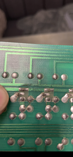
 Looks like it’s transistor 2N3584 (Q21 ) needs to be replaced but it’s a bit of a hack to replace this part as it’s a Unattainable part also replace trans 2N3440 (Q22 ,Q23) while the board is out pinparts sell all the parts to rebuild the high voltage for the display s .
You are using an out of date browser. It may not display this or other websites correctly.
You should upgrade or use an alternative browser.
You should upgrade or use an alternative browser.
Bally Paragon
- Thread starter Dotteddown
- Start date
OP
OP
Hello mate,View attachment 167870 Looks like it’s transistor 2N3584 (Q21 ) needs to be replaced but it’s a bit of a hack to replace this part as it’s a Unattainable part also replace trans 2N3440 (Q22 ,Q23) while the board is out pinparts sell all the parts to rebuild the high voltage for the display s .
Yeah cheers for that I’ve got a tested recon board comimg now so should be ok after this I’m hoping.
In all honesty if I knew that if you swapped the displays for low vault ones and they would work I’d of probably just done this as the ones in mine are original bar one.
I will save the old board for spares I think, or have a go at rebuilding the high voltage section possibly.
The first port of call when you are down in power is to check the rec board which makes the power to the next board in the chain ( sol board )
First port - 10p in the meter @carl lawrenceThe first port of call when you are down in power is to check the rec board which makes the power to the next board in the chain ( sol board )
OP
OP
The one on power supply ?The first port of call when you are down in power is to check the rec board which makes the power to the next board in the chain ( sol board )
I did check this and all tested fine
Go Led - Ive got all colours, red, white, green, blue, amber. Can even mix and match them.
OP
OP
Hi mate, In displays ?Go Led - Ive got all colours, red, white, green, blue, amber. Can even mix and match them.
If I known this I probably would of just gone low vault displays to save it happening again.
I’ve got a tested solenoid driver board on way now at a low cost so I’m hoping this will get them going.
I’ll definitely remember this though !
You live and learn
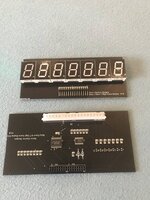
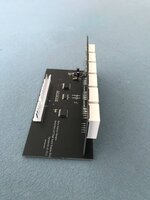
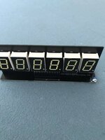
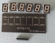
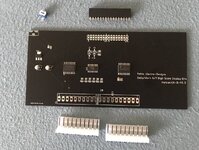
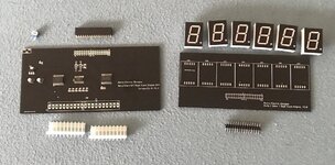
Yes - I make LED display boards , fully assembled, or in kit form (all the SMD components are pre-soldered - just headers and LEDS to solder on)
Attachments
-
 IMG_8337.JPG49 KB · Views: 2
 -
 IMG_8336.JPG48.9 KB · Views: 2
 -
 IMG_8332.JPG64.9 KB · Views: 2
 -
 IMG_8266.JPG114.8 KB · Views: 2
 -
 IMG_8145.JPG125.1 KB · Views: 2
 -
 IMG_8521.JPG73.2 KB · Views: 2
 -
 IMG_8520.JPG77 KB · Views: 2
 -
 IMG_8517.JPG72.6 KB · Views: 1
 -
 IMG_1101.jpeg163.5 KB · Views: 2
 -
 IMG_1100.jpeg168 KB · Views: 2
 -
 IMG_1099.jpeg121.6 KB · Views: 2
OP
OP
That’s good to know mate they look great, infact I remember you saying you put the blue ones in the Electra and i have to say it suits it perfectYes - I make LED display boards , fully assembled, or in kit form (all the SMD components are pre-soldered - just headers and LEDS to solder on)
 Clever stuff
Yes the rectifier board @ TP2 should be +230vThe one on power supply ?
I did check this and all tested fine
I forgot Alan you make the displays , still undesired which colour I should go on my Space Invaders !Go Led - Ive got all colours, red, white, green, blue, amber. Can even mix and match them.
OP
OP
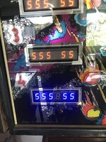
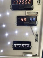
Got to it in the end something in the HV area of the board is shot, fitted a re con board tonight and displays work.Yes the rectifier board @ TP2 should be +230v
Then the right slingshot didn’t work but did with the old board re fitted lol
So got another board comimg from Brain who’s been awesome in helping me sort this what a top bloke
Thankyou Fingers crossed the one on the way will be the closes curtain on this saga

OP
OP
Ohhh space raidersI forgot Alan you make the displays , still undesired which colour I should go on my Space Invaders !
 still my favourite
it’s space invaders. not fridge raidersOhhh space raiders


white or red but not amber - i can do sale or return if you want to try a bunch of different colours?I forgot Alan you make the displays , still undesired which colour I should go on my Space Invaders !
OP
OP
Well guys it’s been a roller coaster week for me in the beginning stage of tackling pinball problems.
Fitted second board sent and all was great displays good and right slingshot good, played about five games and noticed golden falls saucer not firing leading to ball stuck.
Did a lot of testing including a fly wired from earth to q13 and it did fire doing this !
So un soldered q13 out a board it definitely worked off previous and put it in the board golden falls was failing on.
Worked great and thought thank goodness but unfortunately after playing for many hours it still throws up occasionally same fault on golden falls saucer !
Not often it does but when it does it’s totally dead it will only reset after switching off after say five minutes.
Any sooner ball remains stuck !
Think I’ll take q13 out again tomorrow and re solder to make sure it’s .
.
I will also test the two parts against each other in a tester, I knew I should of done this but was too eager to get it up and running.
Especially after seeing no issues in the board I took it from !
Interesting enough when the ball got stuck I decided to give it some tilt ! And scores register so that’s something else to think about tomorrow
Staying patient and learning as I go but loving it
Glad I started on a solid state now
Fitted second board sent and all was great displays good and right slingshot good, played about five games and noticed golden falls saucer not firing leading to ball stuck.
Did a lot of testing including a fly wired from earth to q13 and it did fire doing this !
So un soldered q13 out a board it definitely worked off previous and put it in the board golden falls was failing on.
Worked great and thought thank goodness but unfortunately after playing for many hours it still throws up occasionally same fault on golden falls saucer !
Not often it does but when it does it’s totally dead it will only reset after switching off after say five minutes.
Any sooner ball remains stuck !
Think I’ll take q13 out again tomorrow and re solder to make sure it’s
.I will also test the two parts against each other in a tester, I knew I should of done this but was too eager to get it up and running.
Especially after seeing no issues in the board I took it from !
Interesting enough when the ball got stuck I decided to give it some tilt ! And scores register so that’s something else to think about tomorrow
Staying patient and learning as I go but loving it
Glad I started on a solid state now
Last edited:
hmm check the golden cliffs saucer kick out coil resistance. is it correct? also put a new diode across the coil.
OP
OP
I’m afraid that’s a new one to me Alan, I’m not afraid to try though !hmm check the golden cliffs saucer kick out coil resistance. is it correct? also put a new diode across the coil.
How do I go about that please ?
Is that the diode next to q13 ?
OP
OP
Oh forgot to mention between trying all this out I sorted the gunning on right slingshot, possibly the easiest fix ever just adjusting the gap in contact
Also got lights being temperamental and blowing in top two bumpers replaced them again today and top right was such a tight fit like a Twat I pulled too hard on the whole thing and snapped the solder to wire under playing field
Wedged In place with a screw driver and re soldered as it was to fat a gap to bridge especially with working on playfield wedged up vertically on its flimsy maintenance arm and is now brighter than ever
The old lead solder is noticeably harder to melt and can understand why these go to pot after forty years and solder breaks or cracks , at this rate I feel like re soldering every joint on it
Last edited:
if you’re blowing the tip transistor to a coil it’s either the coil on it’s way out. (shorting it’s windings, so it’s resistance is lower than it should be) or, the fly back diode on the coil itself might be duff. look in the coil. you will see a diode. cut it off and solder a new diode on. they are like £0.10 to buy
OP
OP
I’ll have a look at that cheers alanif you’re blowing the tip transistor to a coil it’s either the coil on it’s way out. (shorting it’s windings, so it’s resistance is lower than it should be) or, the fly back diode on the coil itself might be duff. look in the coil. you will see a diode. cut it off and solder a new diode on. they are like £0.10 to buy
OP
OP
Nothings blowing it’s like an intermittent fault ?if you’re blowing the tip transistor to a coil it’s either the coil on it’s way out. (shorting it’s windings, so it’s resistance is lower than it should be) or, the fly back diode on the coil itself might be duff. look in the coil. you will see a diode. cut it off and solder a new diode on. they are like £0.10 to buy
I’ll still have a look and change all I can to out rule things.
I might even re solder all the pins in that area of the board, I noticed someone had put a new component in next to q13 and it didn’t look great but it must be working ?
Attachments
Intermittent faults are the worst ! You have swapped the Q13 so assume thats ok. check the header connector from the Solenoid Driver board to the playfield
OP
OP
Hi mate,Intermittent faults are the worst ! You have swapped the Q13 so assume thats ok. check the header connector from the Solenoid Driver board to the playfield
Yeah I real pain as you play the game fine for hours and then out of nowhere it happens ! So annoying
I think I’ll take the q13 out as well and test them both this time in the tester, I should of done this first time.
The component next to q13 ill re do as well as it don’t just look right !
The other alternative I could try is replacing the component that drives right slingshot on the first board sent as this worked fine apart from the slingshot !
Just been for a game or ten all works fine ?
I did remember though last night after a few beers decided to take a look at the coin door as all the workings seem to click from inside there.
The coin door never did shut 100% and on closer inspection seems to of been prized open at some point.
I did try to adjust the bolt on the lock and it took me an age to get it to close, what a fiasco
The head of the bolt on the lock mechanism is bent I noticed and this is what’s causing the problem, where I’m going to get one of those I’ve no idea
 might start a thread see if anyone’s got one they want to sell.
 Thread is really thin compared to the head of the bolt
Last edited:
OP
OP
The gunning slingshot was exactly this mate, couple of minutes and all good againCheck the tilt Bob and switches aren't stuck on. The gunning pop bumper is probably a switch that needs adjusting. Be worth reseating connectors on the boards as well just in case.
Happy to pop round and give you a hand looking at it if you want mate, just let me know
just
get a new lockHi mate,
Yeah I real pain as you play the game fine for hours and then out of nowhere it happens ! So annoying
I think I’ll take the q13 out as well and test them both this time in the tester, I should of done this first time.
The component next to q13 ill re do as well as it don’t just look right !
The other alternative I could try is replacing the component that drives right slingshot on the first board sent as this worked fine apart from the slingshot !
Just been for a game or ten all works fine ?
I did remember though last night after a few beers decided to take a look at the coin door as all the workings seem to click from inside there.
The coin door never did shut 100% and on closer inspection seems to of been prized open at some point.
I did try to adjust the bolt on the lock and it took me an age to get it to close, what a fiasco
The head of the bolt on the lock mechanism is bent I noticed and this is what’s causing the problem, where I’m going to get one of those I’ve no idea
Thread is really thin compared to the head of the bolt
OP
OP
I think I will I’ll take a look on eBay or google
Could this affect any of the issues I’ve had or just coincidental?
Could this affect any of the issues I’ve had or just coincidental?
Jam,
I can't access the 3rd page of replies, a blockage for porn appears. What's so suspect? The backglass, maybe.
Re. this solenoid not working, if it's been shown to be the solenoid rather than the switch, and Q 13 the drive transistor has been changed, the associated components may be at fault. There's a diode between the driver transistor and the pre-driver (in U 3 for this circuit), I've seen those cracked, breaking the linkage between them.
If no-one's mentioned it, Test Points 6 & 7 on the solenoid driver are provided to switch the driver and pre-driver respectively, they have the correct resistor values attached to apply 5v to the 'base' terminal of the devices and show if they're okay.
- A lead from TP6 to the banded end of diode CR13 switches Q13
- A lead from TP7 to pin 11 (or the corresponding end of R 65) of the chip U3 switches the pre-driver inside it, and should switch Q 13
OP
OP
Hi Jay,Jam,
I can't access the 3rd page of replies, a blockage for porn appears. What's so suspect? The backglass, maybe.
Re. this solenoid not working, if it's been shown to be the solenoid rather than the switch, and Q 13 the drive transistor has been changed, the associated components may be at fault. There's a diode between the driver transistor and the pre-driver (in U 3 for this circuit), I've seen those cracked, breaking the linkage between them.
If no-one's mentioned it, Test Points 6 & 7 on the solenoid driver are provided to switch the driver and pre-driver respectively, they have the correct resistor values attached to apply 5v to the 'base' terminal of the devices and show if they're okay.
Later versions of Stern's largely similar board even have these points named as such in the screening - 'Driver base probe' and 'Pre-driver base probe'
- A lead from TP6 to the banded end of diode CR13 switches Q13
- A lead from TP7 to pin 11 (or the corresponding end of R 65) of the chip U3 switches the pre-driver inside it, and should switch Q 13
That’s so weird lol maybe it’s the back glass and the way the women dressed who knows lol It’s good that checks are being made though
I’ll definitely try these things as you suggest, thank you for the advice it’s appreciated
Since this post the pin did actually work well through many games and then threw up the same problem just as hit 20,000 on ball one too ! Which really got my back up
I think I may of found something after this with the back box being loose and also the rectifier board being not fixed back due to one wire being short.
I did start a thread on this somewhere ?
