When Hurricane arrived it had battery damage. I gave the CPU board a nice bath in some alkaline killer. But bought a new CPU board to get up and running.
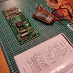
Fast forward 3 weeks and I'm digging into the damaged board.

So far the board doesn't look too bad.
Having been through all the resistors, I have found a few things I don't understand. I wondered if anyone could help?
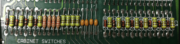
1. R14 - R21
All show as meant to be 10k.

R14 and R15 are. R16 to R21 all show about 1.5k
Did I find some broken stuff? Odd they are all next to each other and show similar resistance.
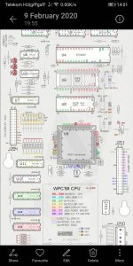
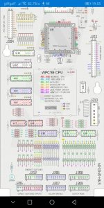
2. R95 and R99
I don't understand the manual here. 0.1ufd ohms
Whaaat?
They both read the same on my meter anyway.
0.725 M ohms ?
3. R91
It's the weird mixing of capacitance and resistance again?
22ufd ? Micro farads?
If anyone can help advise, if you've been through one of these boards yourself, it would really help me out.
Fast forward 3 weeks and I'm digging into the damaged board.
So far the board doesn't look too bad.
Having been through all the resistors, I have found a few things I don't understand. I wondered if anyone could help?
1. R14 - R21
All show as meant to be 10k.
R14 and R15 are. R16 to R21 all show about 1.5k
Did I find some broken stuff? Odd they are all next to each other and show similar resistance.
2. R95 and R99
I don't understand the manual here. 0.1ufd ohms
Whaaat?
They both read the same on my meter anyway.
0.725 M ohms ?
3. R91
It's the weird mixing of capacitance and resistance again?
22ufd ? Micro farads?
If anyone can help advise, if you've been through one of these boards yourself, it would really help me out.
")