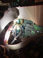
Hi, everyone just looking for a bit of advice on my Bally World Cup soccer pin. Recently acquired from a social club. So it’s had a hard life. I’m trying to get more hands on with the later machines compared to the old em machines which is what I’m used to so please bare with me. I’ve went to plug it in today and nothing happens. You can see in the picture all red leds light up on the power board and stay on and I get partial display on the screen. Just need some advice on where to start first really. Any help is much appreciated thanks all.
Pinball info
You are using an out of date browser. It may not display this or other websites correctly.
You should upgrade or use an alternative browser.
You should upgrade or use an alternative browser.
World Cup soccer 94 issues
- Thread starter Pinball John
- Start date
Check all the ribbon cables
OP
OP
Thanks for the reply. All ribbon cables removed and checked and all ok as far as the eye can see. I also forgot to mention the Playfield has no lights aswell.
You have no leds lit on the cpu so it’s not booting up put some better pics up and check you have 5v to the cpu
OP
OP
You have no leds lit on the cpu so it’s not booting up put some better pics up and check you have 5v to the cpu
No lights on cpu board. Chris. Where do I check for 5v. Sadly no manual to next week now. Thanks
Attachments
OP
OP
PDF good enough?Sadly no manual to next week now.
https://www.ipdb.org/files/2811/Bally_1994_World_Cup_Soccer_Manual.pdf
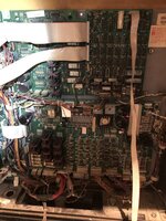
The connector on the right side of the cpu that bridges it to the driver board should have 5v and 12v there it does look like you have some battery acid damage on the cpu can you send a better pic
OP
OP
Perfect thank you
OP
OP
There are signs of acid leak on the holder. But no serious than that. I’ve checked again on the cpu voltage with dc current and I have 11v on the 5v side and 15v on the 12v side. ThanksThe connector on the right side of the cpu that bridges it to the driver board should have 5v and 12v there it does look like you have some battery acid damage on the cpu can you send a better pic
Attachments
Last edited:
Hello,
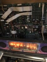
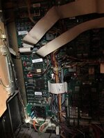
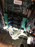
Your picture in post No.6 looks like a power input of the audio circuit board, rather than the main Cpu board - I think that's the Fliptronic II circuit board also visible. I think the DCS audio develops some power of its own from those wires, via the large diodes nearby. DCS also seems to have another power input, visible in post No.5's second picture, below the large capacitors
Which prompts me to ask if the audio board boots up, and signals whether it's okay (or not) by making one 'ting' sound if things are alright. This also (AIR) uses the 12v & 5v produced by the large power/driver board. Maybe only the 5v, maybe both (it looks like both, if that is a power input in post 5, pic.2)
Last edited:
OP
OP
Hello,
Your picture in post No.6 looks like a power input of the audio circuit board, rather than the main Cpu board - I think that's the Fliptronic II circuit board also visible. I think the DCS audio develops some power of its own from those wires, via the large diodes nearby. DCS also seems to have another power input, visible in post No.5's second picture, below the large capacitors
Which prompts me to ask if the audio board boots up, and signals whether it's okay (or not) by making one 'ting' sound if things are alright. This also (AIR) uses the 12v & 5v produced by the large power/driver board. Maybe only the 5v, maybe both (it looks like both, if that is a power input in post 5, pic.2)
Your correct it wasn’t the cpu board. Now I got the Manual I have checked it all. And found a fuse missing. School boy error I know. So have got some 5amp fuse to put in there and will let you know what happens with that. Thanks
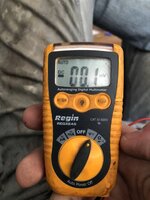
That's good. I'm also worried, though, about your readings of 11v and 15v for the 5 & 12v power rails. In particular, the mention of checking dc voltages with 'dc current' selected on the meter. If it's a typo, then something's wrong with the power circuits. If the meter was set to measure current, connecting it to measure voltage could've damaged the meter*, and wouldn't give accurate readings.
And there are two 12v rails used in this board-set. 12v 'digital' is used for the switch matrix, while 12v 'power' is used for infra-red opto l.e.d's (including flipper buttons) and occasionally for motors. Loss of 12v power doesn't prevent the machine booting up, but any opto switch will be 'dark', rendering it unplayable. F'r instance, with this missing on creature from black lagoon, the two ball poppers kick as the machine resets, because each seems occupied. And even after that, the flippers won't work (from the buttons, anyway)
* in current measurement, a meter has as low a resistance as possible. Connecting it to measure voltage places that v/low resistance between the measurement point and earth, rather than in series, bridging a break introduced into the circuit being measured.
OP
OP
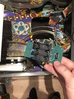
It’s a cheap nasty tester I’ve got. Nothing special. I’m hoping it’s on the right mode. Will invest in something better soon. But I now know why the was no fuse in holder f113 as as soo as you turn it on it starts to boot then the fuse blows. So I’m going to take the board out and have a look at the back and see if I can see anything. But suspecting one of the bridge rectifier could be at fault. Thanks for the helpThat's good. I'm also worried, though, about your readings of 11v and 15v for the 5 & 12v power rails. In particular, the mention of checking dc voltages with 'dc current' selected on the meter. If it's a typo, then something's wrong with the power circuits. If the meter was set to measure current, connecting it to measure voltage could've damaged the meter*, and wouldn't give accurate readings.
And there are two 12v rails used in this board-set. 12v 'digital' is used for the switch matrix, while 12v 'power' is used for infra-red opto l.e.d's (including flipper buttons) and occasionally for motors. Loss of 12v power doesn't prevent the machine booting up, but any opto switch will be 'dark', rendering it unplayable. F'r instance, with this missing on creature from black lagoon, the two ball poppers kick as the machine resets, because each seems occupied. And even after that, the flippers won't work (from the buttons, anyway)
* in current measurement, a meter has as low a resistance as possible. Connecting it to measure voltage places that v/low resistance between the measurement point and earth, rather than in series, bridging a break introduced into the circuit being measured.