What's new
Pinball info

Register a free account today to become a member! Once signed in, you'll be able to participate on this site by adding your own topics and posts, as well as connect with other members through your own private inbox!

Wiring LED star posts to switches

Durzel

Registered
Joined
Oct 1, 2017
Messages
2,041
Location
Bath, UK
Hi,

I'm looking to buy some LED star posts from Comet (along with a load of spare bulbs), specifically these:
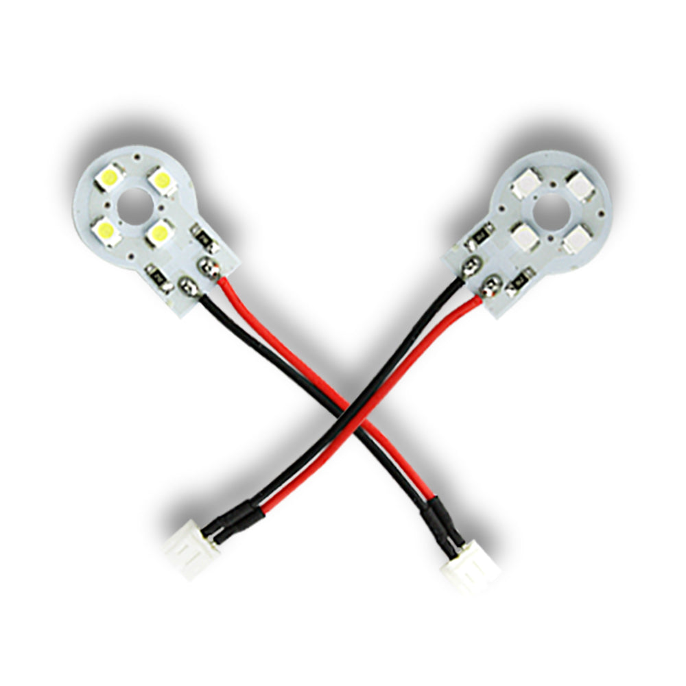

...to go on my TZ mini playfield. I'm looking to wire them up so that they illuminate when a switch triggers they come on, rather than being on all the time via a direct GI connection.

I'm going to replace the switches on the mini PF with ones that provide for two switch contacts, and they have the following config:

rps20180825_082254.jpg

On the basis that the white (WH) and green (GN) are probably for the original loom, how would I go about wiring the secondary switch to trigger a star post LED that only has a black and red wire?

I have no idea what COM (common?), NO and NC mean in relation to wiring these up. I don't want to fry my GI, add AC voltage to the switch matrix or create a new element like Tony Stark, each of which is possible in my case.

Thanks in advance :)
 
NO = Normally Open
NC = Normally Closed.

NC is closed, so the circuit to common is connected until something happens to open it.
NO is the opposite so the circuit to common is open until something happens to close it.
 
Thanks. So in terms of wiring a star post (or any 6.3v LED) with a red and black wire, how would I go about that?
 
No, the boards are a separate thing, supplied by a different seller. The boards basically replace the switches on the TZ mini playfield, and provide a second switch to trigger mods, etc.
 
Ah, OK - I think.

so the green and white are switch wires going back to the matrix.

+ve for the light goes to common, then NC connects to the light (if you want it on apart from new switch is made) or NO connects to the light (if you want it off except for when switch is made)
-ve goes to the other wire for the light.

But you need to check how that board is wired to ensure the power doesn't get through that board to the switch matrix. (connect the mod element and check no voltage is getting to the white and green contacts before you connect in the original switch wires)

Someone a lot clever than me may well chime in telling you differently though.
 
Your instructions seem to imply the star post LED has 3 wires? It only has 2.
 
Yeah, that is a bit confusing to read, I know what I meant in my head.

there should be 2 wires for the LED and 2 wires for the Power for the LED (coming from wherever you are powering it)

+ve for LED (cable 1)
-ve for LED (cable 2)

+ve from Power Supply (cable 3)
-ve from Power supply (Cable 4)

Obviously if you wanted the LED on constantly you would join these wires together without a switch. but you want it to react to the switch so we are putting the switch into one of the cable joins to make / break the connection (start / stop the power flow)

Cable 3 goes to common, then NC connects Cable 1 (if you want it on apart from new switch is made) or NO connects to Cable 1(if you want it off except for when switch is made)

Cable 2 and Cable 4 join together (not on this board, just joined - Molex , solder, twist and tape, whatever really, they just need to be joined for the power to flow).

So if you are using NC:
Power feeds into your board, it flows through the board to the LEd and then back to complete the circuit. When the switch is depressed, the NC element goes open and the circuit is broken so the power doesnt flow.

So if you are using NO:
Power feeds into your board, but there isnt a complete circuit. When the switch is depressed, the NO element goes closed and the circuit is made so the power flows.
 
Last edited:
Gotcha. That makes sense :) Thanks very much.

I guess I need to work out how safe these boards are going to be. There's going to be 8 star post LEDs and 4 of these boards, so there will need to be some splicing of cables as well.

Would I be right in thinking that if I substituted a suitable battery for "cable 3 and 4" I could test the circuit without actually connecting it to GI (since 6.3v is what the bulbs are rated for), and therefore be able to test if there is any voltage across the WT and GN pads (and therefore whether any voltage would go on to the switch matrix) ?

NO is the way I would need to wire it, as the switch is normally open and will be closed by a ball striking the rubber ring, like a regular microswitch (essentially I want the LEDs to illuminate when the switch is closed).
 
Last edited:
yep, Battery will work perfectly as the DC supply. (thats what a battery is :) )
You will need to test between the battery supply and those connectors as well as just between them to be sure nothing is getting to them.
and then test again to be doubley sure once you have connected it into the GI circuit to be 100% sure before you connect the switch matrix in to it.

Can you see the traces on the board? that might show us whether they are completely separate or if both halves are connected in any way?
 
I've bought a few of these post LEDs, so I'm looking to you to lead the way mate! :)

Whats the thinking, run 3 LEDs off the little board and switch THAT?
 
2 LED star posts off each switch, as each switch has 2 of them and there are 4 ... thingys total.

In an ideal world I'd like to be able to connect them all to one GI socket (or more likely solder on a connector so it can easily be removed).
 
I have another question...

I spoke to the maker of the switch mod, and he said the following:

But I believe if you connect directly the star post, you could not see it, because the impuls at a hit is to short.
You need some electronic to make the impuls longer

..which if I understand him correctly means that the LEDs wouldn't illuminate because the switch going on and off would be so quick. Are there ways around this?
 
I’m guessing you would need a timer circuit activated by the switch for say a second or two.
 
I have another question...

I spoke to the maker of the switch mod, and he said the following:


..which if I understand him correctly means that the LEDs wouldn't illuminate because the switch going on and off would be so quick. Are there ways around this?
Not designed for quick flash then. Hadn't realised that either..
 
Ok I've received all the bits for this now, and am keen to install it.

It seems logical to connect it to the GI on the street lamp on the mini playfield so that it's all self contained, but I'm unsure as to how to wire up all 8 star posts in a clean way. I was going to solder a couple of wires onto one of the bulbs in the street lamp, and then add a connector inline so the lamp can be removed cleanly if needs be.

Ideally I'd like to have some sort of board which takes the GI power input and distributes it to each post, rather than having to daisy chain them all together. Does such a thing exist? I found this on the GLM website that looks ideal, but GLM has been out of business for a long time now.

I've found out that the double switch boards I've bought (as pictured in first post) are electrically separated, so that's good.

I could live with the star posts just being on all the time with GI if I can't get the switches to work, the maker of them seems to suggest the pulse from the switch would be too short to illuminate the LEDs. I have no idea how to work around that. Any thoughts?
 
Yeah, that is a bit confusing to read, I know what I meant in my head.

there should be 2 wires for the LED and 2 wires for the Power for the LED (coming from wherever you are powering it)

+ve for LED (cable 1)
-ve for LED (cable 2)

+ve from Power Supply (cable 3)
-ve from Power supply (Cable 4)

Obviously if you wanted the LED on constantly you would join these wires together without a switch. but you want it to react to the switch so we are putting the switch into one of the cable joins to make / break the connection (start / stop the power flow)

Cable 4 goes to common, then NC connects Cable 1 (if you want it on apart from new switch is made) or NO connects to Cable 1(if you want it off except for when switch is made)

Cable 2 and Cable 4 join together (not on this board, just joined - Molex , solder, twist and tape, whatever really, they just need to be joined for the power to flow).

So if you are using NC:
Power feeds into your board, it flows through the board to the LEd and then back to complete the circuit. When the switch is depressed, the NC element goes open and the circuit is broken so the power doesnt flow.

So if you are using NO:
Power feeds into your board, but there isnt a complete circuit. When the switch is depressed, the NO element goes closed and the circuit is made so the power flows.
Can you please clarify the wiring in your post, as it looks like cable 3 is not connected to anything? Thanks :)
 
Oops. It should be:

Cable 3 goes to common, then NC connects Cable 1 (if you want it on apart from new switch is made) or NO connects to Cable 1(if you want it off except for when switch is made)

I'll edit my original post as well.
 
Would something like this work to distribute power to the 8 star post LEDs?


That looks close.. outputs at 3v and 12v though? Be nice for 12v led strips?

I've sent a note to GLM, they might be no longer trading, but might be happy to send left over stock if they have it.

A board for this type of thing would be handy in any event. Let's design and make one! @myPinballs do you know of a solution for this challenge?
 
I found an alternative board which is more practical I think, and should be able to fit on the underside of the mini playfield:


Don't need all the settings that are on the other one. GLM won't reply, the guy has stopped doing anything pinball related for a long time, sadly.

I'm wondering now where to tap in GI voltage.. the street lamp seems like the obvious place as it's all self-contained then, but at the same time it's very crowded in there with 2 GI lamps and a flasher (which runs on a lot higher voltage).

TwilightZoneLamp_2015_01.jpg

(not my lamp)
 
Last edited:
I need a picture. 👍 (Now see picture, wasnt pulling through)

The board you mention above, just connects everything? Same power out as same power in?Could you wire out from lamp and install the board a bit further away and run wires back to the LEDs if it's right spot?
 
Last edited:
I'm going to have a crack at removing the mini playfield this weekend. Then I'll know what I'm doing with it I think.
 
Back
Top Bottom