What's new
Pinball info

Register a free account today to become a member! Once signed in, you'll be able to participate on this site by adding your own topics and posts, as well as connect with other members through your own private inbox!

Williams system 11C Power board. Help needed.

Cai Remrod

Site Supporter
10 Years
Joined
May 6, 2012
Messages
27
Location
Warwickshire
System 11C Powerboard.

Set up and switched on the game after a few years in storage. Nothing happens.

Replace a few blown fuses. They dont blow again. But still nothing.

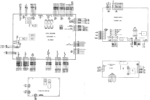
Check the power board. +5v ok. +12v ok. BUT -12v reads -2.3v.

Look at the schematic. Seems that BR and C9 are the only components going through -12v. Changed these components. -12v now reads -14v (probably ok) BUT after 30 seconds, reading drops back to -2.3v.

Thats where Im at.

Can any techie on here suggest what else could be wrong?

Any advice and suggestions very welcome.

Thank you.
 
-14v should be ok.

Is anything downstream connnected to the PSB? If so disconnect everything except power inputs.

Is the -14 V to -2.3 V repeating itself? Do you get -14 V every time you power on and then it drops to -2.3 V after 30 s or is it again remaining at -2.3 V with the new components?
 
-14v should be ok.

Is anything downstream connnected to the PSB? If so disconnect everything except power inputs.

Is the -14 V to -2.3 V repeating itself? Do you get -14 V every time you power on and then it drops to -2.3 V after 30 s or is it again remaining at -2.3 V with the new components?
Andy,

If I switch off/on, I still get -2.3v. If I leave it until the next day(?), it repeats itself, ie -14 to -2.3.
 
Remove anything connected to J1 and J2 and test the voltage again. J1 & J2 are the outputs from the power board, J3 is the inputs to it from the transformer.

The PSU circuit for the +12v and -12v is pretty simple:

TP2 to TP3 should give +12v and TP2 to TP4 should give -12V (In both cases the black lead of your DMM to TP2 which is Ground).
1668446653724.png
 
Remove anything connected to J1 and J2 and test the voltage again. J1 & J2 are the outputs from the power board, J3 is the inputs to it from the transformer.

The PSU circuit for the +12v and -12v is pretty simple:

TP2 to TP3 should give +12v and TP2 to TP4 should give -12V (In both cases the black lead of your DMM to TP2 which is Ground).
View attachment 186704

Hi Alan,

Yeah, agree, the circuit looks pretty simple. Thats what is so frustrating!

Test has been done with J1 and J2 disconnected.

Any ideas what could cause it??

Cheers,
 
check you are getting 9.7v AC on both F4 and f5 (both ends) compared to ground (TP2).
is c9 wired up with the right polarity?
 
... to help me sort out this mystery.

In answer to your queries,

Getting 11.6 vac on F4/F5.

Doublechecked C9 and BR. Both are installed correctly.

The machine has not been switched on for 48 hours, so I thought I check timings again.

-14v for 2 minutes, then drops to 3.6v and slowly reduces to 2.3v over the next 5 minutes.

Any ideas as what to do next??
 
when it drops what are the ac voltages on F4 & F5
Still the same. BUT.... I have discovered that 5v line starts ”flickering” when it is dropped so I am going to change the voltage regulator unless you think differently.

Will order it now and report back in 3 days or however long it takes to get here.
 
Only thing left would appear to be ground. Do you have a good connection to ground from the BR? Is it still good when the voltage drops?
 
Have you changed C7 already? If not, replace or remove and report back.
 
Have you changed C7 already? If not, replace or remove and report back.
Changed C7. No improvement.

Didnt have a 100mf 25v (as specified). Used a 100mf 250v as from memory it should be ok as long as V is not lower than specified. PLEASE tell me if this is wrong!
 
Here’s a really good site for troubleshooting System11, the game manuals are also excellent for solving problems.

Thank you for your reply. I did find this site before posting here. Hence I changed C9 and BR.

I am now waiting for the 6057 to arrive. I cross my fingers! 😃
 
Higher voltage tolerance is absolutely no problem. What I don’t get is that the voltage needs to go somewhere. Can you measure AC on the -12 V against ground please?
 
Higher voltage tolerance is absolutely no problem. What I don’t get is that the voltage needs to go somewhere. Can you measure AC on the -12 V against ground please?
AC on -12 and ground reads 0.001.

Have now changed the 2N6057. Fiddly (😃). No change! Grrr! Wtf!
 
If there was a problem with the 5v side then you’d expect that to interfere with the +12v rather than the -12v unless it’s messing with the ground voltage.

If the 2 AC lines coming in are maintaining their correct voltages + /- 10v (or thereabouts) then the only thing that could mess the -12v up is c9 or br1.

i’d disconnect temporarily one wire to c9 and see what happens.
 
Don‘t get how the -12 go to 2.3 without the BR burning up. Maybe the 5V move the operating point of the bridge somehow? Would need ground to be bad though as suggested by you.
Just to make sure: can you measure resistance from TP2 to the ground lug on your power cable? Should be near zero. If so, try without C9 as suggested by Alan. Next, Iöd change the BR again.
 
Just done about 8 System 11 games in a row in my workshop (that is Birmingham based if you are stuck!). Have Radical set up at the moment :)

I had one voltage missing and it was on the top of the PCB under the rectier.

I think it was the -12v.

However that would not stop the game from booting and working. The -12v is only used on the sound from memory.

I would be looking at batteries (if you left them in!) for any leakage.

Also some caps go bad.

You only need 12v 5v and ground for the main MPU to boot.

The high voltage runs the displays only.
 
Don‘t get how the -12 go to 2.3 without the BR burning up. Maybe the 5V move the operating point of the bridge somehow? Would need ground to be bad though as suggested by you.
Just to make sure: can you measure resistance from TP2 to the ground lug on your power cable? Should be near zero. If so, try without C9 as suggested by Alan. Next, Iöd change the BR again.
Been unable to work on machine for a few days, so sorry for delay in replying.

Resistence between TP2 and power cable ground is all over the place. No solid reading. Jumps and gives various values between 4 and 35 ohms (aprox).

Does that give you a clue?
 
That isn‘t helpful for sure. Can you measure resistance from TP2 to backbox ground? Also, voltage between TP2 and backbox ground. Needs to go somewhere :-).
 
That isn‘t helpful for sure. Can you measure resistance from TP2 to backbox ground? Also, voltage between TP2 and backbox ground. Needs to go somewhere :).
Ok,

Right side ground braid to TP2, 0.001 ohm switched off. Once mc on, goes to 1 ohm.

Left side ground braid, fluctuating!

Voltage 0 vdc.
 
Back
Top Bottom