Hi guys ok small issue my whitewater has been throwing around whirlpool awards without me hitting the whirlpool , I’m switch test it’s showing my lite lock targets are also activating popper and wirlpool exit , can anyone tell me why?? Thanks
Pinball info
You are using an out of date browser. It may not display this or other websites correctly.
You should upgrade or use an alternative browser.
You should upgrade or use an alternative browser.
Whitewateargggggggg
- Thread starter The seeker
- Start date
I’d be checking diodes mate. There’s a clever matrix to figure out which ones to check but I’ll leave that to the suits.
Check the lock targets and the whirlpool ramp entrance as a starter
Check the lock targets and the whirlpool ramp entrance as a starter
@The seeker Can you please document the affected switches and their relation, i.e. pressing left lock also activate whirlpool exit, etc. What happened in the run up to this problem? Did you work on the machine, if so what?
OP
OP
Hey dr hex , just researching this at lunch thanks for making contact ,
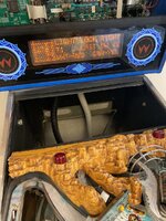
Ok so when go into switch test if I press lock on either side of vuk it registers as switch 41- 61 popper - lock
And the right 42-62 wirlpool exit , lock
I just can’t figure out why I’m getting 2 different contacts when I’m only pressing one switch. Tbh I’ve noticed that the wirlpool awards have been just randomly called out which led me to think maybe a dirty opto in subway so took that out and cleaned, then took out the vuk no way out and cleansed those , it’s pretty grubby . Anyways I still have the same issue as before I did this , the double switch registering lock targets. All wires seem intact
OP
OP
OP
OP
OP
OP
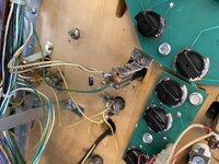
Those 4 switches form a box if you look at the switch matrix. Classic sign of diode gremlins. As @Spandangler said need to check the diode on each switch.

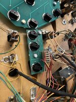
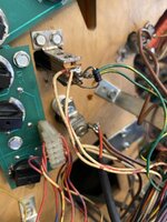
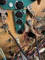
Manual says white brown/green yellow for switch 41, your photo shows white brown/green blue, or am I missing something?
Manual says white brown/green yellow for switch 41, your photo shows white brown/green blue, or am I missing something?
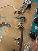
I don’t see that ..,The photos show green yellow at both lock switches as expected .
OP
OP
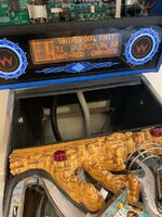
Could I ask which mech is the wirlpool popper ? Is that the no way out popper ?
Could I ask which mech is the wirlpool popper ? Is that the no way out popper ?
No
It's the one that kicks it out of the Lost Mine.
OP
OP
I’ll take a look there too
OP
OP
Ok so both wirlpool popper : lost mine , and wirlpool exit - subway optics only register there own activation ie no double switching si it’s just why the two stand up targets are registerering two switch’s ??
OP
OP
Hi, no they just do left and right loop
OP
OP
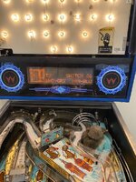
That’s your 8 Optos all showing Closed which is what you would expect. Plus Switch 24 which is the Always Closed.Switch level test.
OP
OP
Afternoon folks I honestly can’t think when it began , It’s been irking me for a while that wirlpool call-out were being shouted and awarded without doing the move . Hence I started a switch test then discovers the double switch. , I’ve not removed or added any parts all diodes are the same as they always were / tho I can’t check them without multimeter.
OP
OP
Rushed off to screw fix yesterday , bought a multimeter, came back decided to have a quick game and lo and behold , zero wrong call outs … all perfect! So now to I poke the bear or do I say if it ain’t broke … ahh pinball you make a sane man mad and a mad man sane
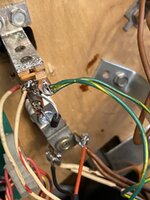
I reckon you have a leg on a diode which has come unsoldered. It periodically makes contact with the switch tab and occasionally works.
OP
OP
OP
OP
You sure I replaced like for like ? I can give it another later
OP
OP

OP
OP
Ok I’ll fill them over , tbh wiring diagrams might as well be printed on the side of a pyramid, I can’t make head nor tail of them I get by on like for like but I’m happy to give it a try thanks
OP
OP