What's new
Pinball info

Register a free account today to become a member! Once signed in, you'll be able to participate on this site by adding your own topics and posts, as well as connect with other members through your own private inbox!

Complete Whirlwind playfield swap

kev a

Site Supporter
Joined
Jun 4, 2019
Messages
671
Location
Guernsey
Been waiting for the weather to warm up a bit before taking on this playfield swap, well, that’s what I have been telling myself, in all honesty I’m a bit intimidated. The playfield is a CPR I brought at the end of last year and its been waiting patiently in its box ever since.

First up, knocked up a couple of rudimentary playfield stands, as an utter newbie I’m trying to do everything possible to make the job easier, so having the ability to have the playfields side by side seemed like a good idea.

20210318_130950.jpg

Next job was getting the old playfield out of the cab, the labels were still on all the back box connectors so that was just a case of unplugging and feeding through the hole, so with the help of a glamorous assistant, the playfield came out without too much drama.

First job on the new playfield was giving the underside a good coat of varnish, went for some Matt Rustoleum Polyurethane Finish, apparently its suitable for spraying directly onto wood, and that’s exactly what I did with it.

20210318_121026.jpg

Next up were a couple of jobs I have been really dreading, installing the t-nuts and countersinking the pop bumper nails. In the end I went with the good old hitting them in with a hammer approach. A couple of thoughts here, most of the holes were very tight and needed redrilling, it’s also quite hard to see which are the 8-32 inch and which ones are the 6-32 inch t-nuts on the old playfield.

20210320_122437.jpg

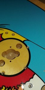
Countersinking the pop bumper nails didn’t turn out as bad as I had expected, not sure if it helped or not but I warmed the area with a hairdryer first in an effort to soften the clear coat and hopefully make it less likely to crack, going slowly and checking the depth with the head of the nail seemed to do the trick.

20210319_111306.jpg

After this I really wanted to get the side rails installed to help minimise any flex in the playfield, which to me seems important with WW and the three large holes in the middle.

After this was installing the guide rails, before removal I wrapped a socket in tape until it fitted snugly under the rails and used this as a measurement when putting them back in, so I wouldn’t bash them too far in by mistake.

20210320_115911.jpg

For these I drilled a hole slightly larger than the rails themselves a couple of mm into the clear, I read somewhere it’s a good idea to give them a tiny bit of clearance, so when a fast ball whacks them they aren’t pushing on the clear and risking cracking, I dunno, seemed to make sense so went with that method.

Then onto moving across the flippers and giving them a rebuild while there out.

20210320_124044.jpg

20210320_134640.jpg
A couple of lighting pcbs moved across without too much trouble, then onto the slingshots.

Rather annoyingly the hole for the star post on the left seems to have been made a little bit off, If this was anywhere else on the playfield I would have just gone with it, but being in such a prominent location, It would have bothered me, made up a template to try and drill the hole slightly more to the left, it worked ok, and now is in a similar position to its mate on the right.

20210320_173253.jpg

20210320_174231.jpg
20210320_175124.jpg

That’s about where I’m at right now, hoping to get some more done over the next few days so will keep posting progress.
 

Attachments

  • 20210319_105315.jpg
    20210319_105315.jpg
    55.9 KB · Views: 17
Nice work and kudos for getting started, I've got a Taxi from CPR to do it's been sitting airing in the back room since September I'll be following your thread with much interest.

Good luck with the remaining to jobs.
 
You need to drill out all the ball guides and post holes on most playfield if it’s a micro playerfield you will probably be missing a post hole near the scoop
 
Thanks for the kind words guys, managed to get a bit more done today, although it probably doesn't look like much progress, cleaning everything seems to take an age.

Started off by getting the cellar mounted, I wanted to take care here as its really important when the ball exits the cellar it lands on the left flipper and doesn't bounce on the slingshot, went with using some transparent sticky plastic to mark out the holes on the old playfield and copy them across.

20210321_125519.jpg

Also gave them a good clean and polished out the ball marks with wire wool.

20210321_124729.jpg

Looking nice with the cliffy protectors

20210321_192025.jpg

Managed to get the spinning mechanism installed too, needed a good clean as it looks like it had been greased in the past.
I really wanted to get it lined up the best I could before making pilot holes so resorted to resting it on the upside down playfield and laying on the floor looking upwards to check the alignment 😁

20210321_131915.jpg20210321_132241_HDR.jpg20210321_141805.jpg

The spinning disc decals are still in nice condition so I'm not going to be replacing those.

20210321_192036.jpg

Then onto the 3 bank opti target, which went smoothly, seem to be the one case so far where the marking supplied by CPR worked out just fine.

20210321_151019.jpg

Cleaned and replaced the end of stroke switch on the upper flipper, in hindsight I should really have ordered a rebuild kit for this one too. I'm afraid I forgot an after pic.

20210321_160234.jpg

Had a bit of trouble with the saucer kick out mechanism. its a busy area with the switch and the arm both close to each other, copied across the existing hole pattern using the sticky plastic method as the CPR markings were way off, however it seems that position is far from ideal, I reinstalled back into the old pf to make sure I hadn't messed something up, but it seems like the coil was installed too close to the arm mechanism from factory and was binding, luckily that's one area with plenty of room, so drilled a few new holes and mounted it a bit further away. seems to function much more smoothly now and the extra holes are hidden under the mounting bracket, so nobody will know about my mistake :D

20210321_170244.jpg

20210321_191928.jpg

So that's where I'm at tonight, backs killing me so going to call it a day for now.
 
Whirlwind is simply a great, properly designed and manufactured game.

Just look at the 3x spinning wheels, with individual height adjustment on the things. The mech is unique to whirlwind. Still spinning after tens of thousands of games and 30 plus years of service.

I wonder whether this level of build quality will ever be repeated.
 
Yeah I know what you mean, after a cleanup you wouldnt believe that mechs 30 years old. It really came up like new. I really like the ramp mech with a little mini solonoid to control the locking mechanism.

Although after a day of working on pop bumpers I do feel like slapping Pat Lawlor for putting six of the darn things on there
 
Made quite a bit of progress over the last couple of days.....

Test fitted the ramp mech, I really want to check the operation with the ramp installed, so have only drilled a couple of holes so far, just in case it needs adjustment.
20210322_120144.jpg

Then went to work on swapping over the pop bumpers, this for me was one of the trickiest parts of the swap so far, its a very busy area, and its really hard to see whats going on, one mistake I made here is not buying new bumper light sockets, I think leaving the old ones in place to copy would have made things easier, ended up marking the route on the old PF to give me something to work from


20210322_133939.jpg

20210322_170744.jpg

Decided to leave the pop bumper switches as part of the harness and move them with the rest of the sockets and switches.

Reinstalled the pop bumper coils then assembled the pop bumper bodies, went for clear pop bumper bodies and skirts, might not be for everyone but really liking them so far.

20210322_202646.jpg

Then onto a bit of a tedious task, just numbering the insert lights and switches, and writing their locations onto the old PF as a reference, although its probably overkill, like others have said the harness kind of falls into place and its mostly obviously where everything goes, although I did have to resort to it a couple of times in tight areas.

Moved the harness over onto a piece of cardboard.

20210323_124233.jpg

Then moved onto the new PF and started screwing all the inserts, gi sockets targets and switches.

20210323_150213.jpg

20210323_191714.jpg

So that's where I'm at tonight, about 2/3 of the underside wired up now, hoping to get that finished up tomorrow and move onto the top side.
 
Thanks guys, came across a massive problem this morning though, seem to be missing the cut-out for the shooter lane switch, guess im gonna have to get the wood saw out?
20210324_122459.jpg16165888048004491150878755358177.jpg
 
Last edited:
I have emailed CPR to see what they say, I have considered using a straight edge and a router to make the hole, but very nervous. about fracturing the clear coat, has anyone had to cut a large hole in a new PF before? any tips?

Honestly I was looking forward to reaching the end of the project and now feeling a bit dejected, and cross with myself for not spotting this sooner.
 
Yeah I'm not best pleased, I was always expecting to drill the odd hole and stuff, I understand these things aren't always 100% and need some fettling, but that takes the mick, if making the hole goes wrong, that's a $1000 PF down the drain!
 
Bit of an update, have had a chat with CPR, who to be fair, have been very helpful, firstly they offered an exchange for another PF, which I declined, as the thought of undoing/redoing all this work filled me with dread.

The chap I was speaking with spoke to the boss and they are sure if the hole is cut with a brand new router bit there should be no problem with the clear coat fracturing.
They have also offered a partial refund as they agree the PF shouldn't have gone out with the cut missing.

I'm fairly happy with the situation as it stands and have ordered three new router bits, 4mm, 5mm and a 3/16" which I think is what the cut would have been made with, just deciding whether to go slightly smaller with the 4mm to allow some extra material for sanding afterwards.
 
Update incoming......

Bit the bullet and cut the shooter lane slot with a router, apart from cutting my thumb with the new router bit (note to self, new router bits are sharp) everything went smoothly, bit of measuring and clamped a scrap of wood to use as a straight edge, went a bit smaller than the factory groove, as the only size I could get locally was 3.2mm (factory is 4.7mm or 3/16") and hand sanded to remove a little more.

20210326_135047.jpg

20210326_135855.jpg

Then onto installing the more ball guides, heres a thing to note, the ball guides have bolts that taper out at the end, not sure why? but the pre drilled holes don't seem to have enough clearance for this part, it may be that screwing them down tight works, but being a wimp and not wanting to fracture the clear, I have been opening up the sides a bit with a normal 3mm drill bit.

20210326_163246_HDR.jpg


20210326_163252.jpg

Here's another "gotcha" with ball guide fitment, something that I had been aware of from reading other peoples swap experiences, there doesn't seem to be enough room for the top ball guides and the metal posts, I'm sure there's some way to move the hole, Dremel the guide or something, but for a couple of quid you can get these slimmer guides, that fit just right, OK its not factory correct, but far easier and less risky.

20210328_125514.jpg

20210328_125542.jpg

More guide rails installed, having read horror stories about clear coat fracturing and problems with fitment I was quite apprehensive about this bit, but honestly didn't have any problems at all. So I think any issues in this area must have been addressed by CPR with the later PFs

20210328_172103.jpg

One of the upper plastics was busted, I was 100% sure I hade ordered a replacement, searched high and low, resorted to checking the invoices from bits I ordered, and nope must have forgotten.

So made up this ropey repro plastic to go in its place, not a serous attempt at a repro, but at least its something to go there for now until I get round to ordering a replacement.

20210328_133520.jpg

Then onto installing the ramps, the left ramp was a new repro and I had a bit of trouble installing it, the repros seem significantly thicker and less bendy than the originals, I would have liked to have positioned the ramp entrance a little bit closer to the yellow pop bumpers, its a couple of mm higher than on the old PF, but with the ramp entrance being secured with just 2 little screws I was a bit apprehensive about forcing the ramp too much and putting too much pressure on the screws.

I will see how it plays, and possibly revisit this in a few month once the ramp had some time to conform to its position.

Got the main ramp in place, still need to hook up the ramp mechanism and make sure its operating smoothly.

20210328_213334.jpg

The finish line is in sight now 😎
 
Good job on the cut, that would've had me terrified!

Re the ball guides, I like to put a washer there - also stops the ball guide from digging into the clearcoat.
 
Thanks dude, yeah was a bit nerve racking, I was imagining the worst case, sneezing or something and cutting the PF in half :eek:

That's a good idea about the washers, had to remove one of the ball guides to fit a post and it had made a mark in the clear, I have them nipped up snug, but haven't gone overboard tightening them.
 
Finished up the last few bits last night and got the PF into the cab, wired up and powered on, couple of inserts out, but turned out to be a lose connection on one of the light PCB's and a couple of LEDs just needed adjusting in their housings, also had a bit of a head scratcher, as the GI lighting on the top of the PF didn't seem to be working, turned out one of the wires has come out of the IDC connector that plugs into the interface board, its kind of wedged in for now, but going to order an insertion tool and try and get it back in properly, still a couple of bits left to do like install the apron give the PF a good wax and tidy the back box wires a bit, but......

It lives!

20210329_222542.jpg

Couple of arty shots....

20210329_222753.jpg

20210329_222804_HDR.jpg
 
Approximately how many hours was that start to finish Kev if u don't mind saying?
 
No I don't mind at all, urm Lots! :)

I took 3 days off work last week plus 2 weekends, so around 7 full days plus a bit each evening I would say around 50-60 hours in total, although I'm not the most organised worker so a good amount of that was looking for tools that had been misplaced. Cleaning things takes a lot more time than I was expecting, I can see how people who tumble every bolt, wash the harness etc spend 100+ hours on a swap.
 
Hey Kev, looks great! I've not logged onto the forum for a few months, I moved house before Christmas and all my pinball stuff has been packed away whilst getting everything sorted but started getting it ready now to continue the restore so really glad to see this thread!
I'm just in the process of building a PF rotisserie but after looking at your pics I'm thinking I actually need to be building two!

I've just had a look through my previous photos and see that my PF has the same fault, i.e. no cutout for the shooter lane switch. Glad I saw this and thank you for taking one for the team, I guess first job is get a new router bit and cut the slot out...
Any particular reason you varnished the back of the PF or purely cosmetic?
 
Hi Ben thanks :thumbs: Congrats on the house move, a PF swap is way less stress than moving house, so your on the home straight now. :)

I guess having 2 rotisseries isn't strictly necessary, but honestly I wouldn't consider doing a PF swap without, the angled metal I used came in 2m lengths, so making an extra one only cost about £8 more for a couple more lengths of wood, and once all the tools were out, didn't take much longer.

Let me know if you need a router bit, the 3/16th router bit I ordered online took too long to arrive, so never actually ended up using it, happy to post it to you if you need one.

I varnished the underside as a couple of posts online mentioned it makes cleaning coil dust easier, it gives the wood a very mild sheen, but nothing too obvious. One of the upsides is when marking out measurements for the plunger lane cut in pencil, the marks came right off afterwards with a rubber, so it does seem to make cleaning a bit easier.

A couple of more things I would really recommend is getting a new set of pop bumper bulb connectors, (I didn't do this but wish I had) they are a pain to straighten and re use, also the slimmer posts for next to the ball guides in the upper part of the PF, these are a must, as the originals just wont fit without modification.

Any questions feel free to fire them my way, I still have a couple of bits left to do on mine before its 100% complete, managed to stand on one of my shiny new pop bumper caps and snapped a slingshot rubber, will post up some more pics once replacements arrive and get installed.
 
Last edited:
Thanks Kev that's very kind of the offer on the router bit, happy to pay you for it of course. My first thought was whether I could get away without cutting the slot, perhaps by building a little inductive sensor board to detect the ball without needing a switch. The thought of taking a router to the PF is a bit nerve-wracking!

A second rotisserie makes sense, originally I was thinking just strip the old one down then rebuilt the new, but having the old for reference and swapping over is a good plan. Shouldn't take much effort to knock up a second one. Good advice on the pop bumper connectors and posts etc, I'm glad you've done the job before me lol.

Ben
 
Its cool no need for payment, let me know your address and I can get it in the post for you, its an odd size so I cant imagine I will ever use it for anything else.

Yeah I was the same, its the kind of cut you wouldn't think twice about doing normally but with a £800 PF its a bit nerve racking. But to be fair the router method worked out well enough. Bit like going to the dentist, the anticipation was the worst part, then afterwards I was thinking that wasn't too bad.

The new GnR uses sensors without traditional switches I think, so I'm sure something along those lines would be possible. These repro PF's have a much shallower shooter lane and the ball sits inside the slot when launching, unlike the factory PF where the ball is resting above, I'm not sure how not having the slot could effect ball launch, possibly it could jump sideways, or not sit correctly for the plunger, probably wouldn't be an issue but worth considering if you go down that route.
 
Thanks Kev that's very kind of you, I'll drop you a PM.
I also contacted CPR about it and they told me they are probably 5 or 6 playfields like this out in the wild but have only so far identified the owners of around half of them. They had a problem with the CNC tool (sounds like the cutter had snapped) and the mistake wasn't realised until they were contacted about the issue. They also offered me some money back for the inconvenience, and suggested the slot could be cut using a table saw. Seen as I don't have a table saw I shall use the router method like you did!
 
Finished the last couple of little jobs, so marking this project as done :D

Was getting intermittent issues with the little multiplier insert board, turned out all the pins on the header had cold solder joints, was fine before, but the stress of reseating the connector must have finished them off, 2 mins with a soldering iron sorted it out.

20210414_155220.jpg

Also added a yellow star post LED to the middle star post behind the three bank stand up target and added a flexible LED to the GI to illuminate the saucer at the back, really like the look of this as its an important shot, and having it in the dark hiding under a ramp, its kind of hard to see.

Also had to move the ball guide that feeds the upper flipper, firstly with the flipper extended the ball guide was touching the rubber, and secondly with the ball running around the orbit it wasn't feeding cleanly to the flipper bouncing off the back, making the ramp shot hard, filled the original hole with bamboo stick and super glue and redrilled moving the ball guide out slightly.

20210415_091900_HDR.jpg

Then new rubbers on the upper left slingshot (not sure what its actually called as its not really a slingshot) and yellow bumper cap to replace the one I stepped on :mad:

So that's it for now at least, all done and with the adjustments to the upper flipper guide now playing better than ever....

20210414_183910_HDR.jpg
20210414_183831_HDR.jpg
20210414_183819_HDR.jpg
 
Back
Top Bottom