What's new
Pinball info

Register a free account today to become a member! Once signed in, you'll be able to participate on this site by adding your own topics and posts, as well as connect with other members through your own private inbox!

Whirlwind 3 bank drop target issue

Spandangler

Site Supporter
10 Years
Joined
Jul 21, 2011
Messages
6,778
Location
Suffolk
Me again!!

Strange behaviour with the three bank opto targets.

I’ve replaced middle and bottom optos as they weren’t registering in test. They still don’t.
I’ve reflowed headers. Checked all diodes and resistors. All seem fine. There’s a chip on the board. I don’t have a logic probe to test.

Is there much else to go wrong on that board?
Any techies know of any methods to check to see what has failed?
I can buy a new one but would like to fix this if I can.
Cheers all
Gaz
 
Yo Gaz

You *def* got good connection from opto board back to the brains ?

I only suggest this as just today connections were the culprit for my game meltdown. And also because it’s always fricking connectors 😂

Non Techie GrizZ melting on south coast
 
I’m assuming so mate. It was fine. One of three registers.
I’ll have a proper poke about later. I’m losing the will to live with it.
 
TAke the connector off, and whilst in switch test, short the column pin ( 7 green ) to 6 5 and 4 in turn which are the three rows. If each respond then the fault is with the board. If not then its contnuity to the cpu.

The chip is an LM339 comparator, and they do fail easily if they get a voltage spike.
 
Last edited:
Smashing thanks Andy. I assume you mean short the pins on the cpu?
TAke the connector off, and whilst in switch test, short the column pin ( 7 white ) to 6 5 and 4 in turn which are the three rows. If each respond then the fault is with the board. If not then its contnuity to the cpu.

The chip is an LM339 comparator, and they do fail easily if they get a voltage spike.

Sorry Andy. Did you mean the connector on the cpu? J10 ?
Or the connector itself from the opto board?

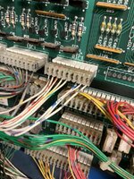
The cpu connector at J10 which has the same wire colour looks like this
IMG_0961.jpeg

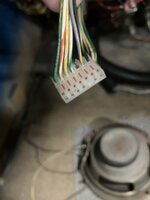
Opto board connector looks like this

IMG_0962.jpeg
 
On the latter picture. You’re testing to see if you have continuity to the cpu from that connector. If you do then you be only have the board to suspect. In the picture the column is the green wire and each switch is on one of the three wires adjacent.

In my first post I said white wire when it should have been green.
Gotcha thanks mate
 
Not sure if it's the same but I have a opto board from a Hurricane, I think it's 3 bank?
 
I have four of these boards between taxi and diner but they all utilise the other header pins which are absent from mine805DD226-541B-446A-8192-80E7C9158FA1.jpeg
 
Ok I’m at a loss. Doing my nut now.

Only opto 3 registers in switch test.

I’ve replaced optos 1 & 2.
I’ve reflowed header pins.
I’ve replaced U1 LM339.
I’ve checked each resistor and diode
I’ve done as Andy suggested and shorted the row/ column which registers fine in switch test

Are there any other checks I can do with a dmm before I throw in the towel and order a new one?
 
swap opto 3 for one of the other 2 - see if the problem moves?

check for broken traces,

check continuity from the connector cables to the relevant components on the pcb to check that header is making good connections?
 
Thanks Alan. Will try those things. Those optos are such a **** to get off without obliterating them. Maybe another day. I’m over it today 😆
 
Just change the optos for new that aren't working as an easy rule out scenario if you've got stuck trying to diagnose. Dont bother removing an old one and reinstalling it. Might be the lm339. they do wear out, but you need to logic probe it all to fathom it out.
 
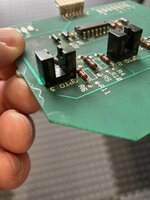
I’ve swapped the known working opto to another slot and it works in there so I can only assume the optos I’m using are incorrect? Duds?

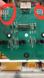
I’m assuming the printed dot on the opto housing correlates with the printed dot on the pcb image.jpg
 
tried it the other way round. No dice.
God knows. I’ve ordered some new ones so fingers crossed they work. This board is like Triggers broom now
 
New optos no change. Still not working. I admit defeat and buying a new one. If nothing else my soldering skills have come on.
It’s weird. If I plug the connector in during switch test it registers the optos which don’t register if you interrupt them as of they are being activated
 
Back
Top Bottom