Pinball info
You are using an out of date browser. It may not display this or other websites correctly.
You should upgrade or use an alternative browser.
You should upgrade or use an alternative browser.
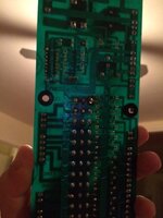
What headers are these???
- Thread starter Paul
- Start date
Can you not just replace them with molex?
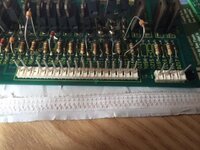
Looks like they are, however round pin as opposed to standard...
So - i recon they are 0.156" Round pin Molex....
So - i recon they are 0.156" Round pin Molex....
P
Pinballdoctor
MTA156 from mouser will be a good replacement
They do look to be in very good condition so I'd take them off the board, give them a quick clean and put on the new board... 
I'm sure you're on the case but it's worth saying.... I'd also take a look at the circuits that caused the original meltdown and see if you can figure out what happened to try and avoid a repeat with your new board... you might need beefier resistors or transistors on that board or improvements to be made elsewhere.
I'm sure you're on the case but it's worth saying.... I'd also take a look at the circuits that caused the original meltdown and see if you can figure out what happened to try and avoid a repeat with your new board... you might need beefier resistors or transistors on that board or improvements to be made elsewhere.
- Joined
- Jul 21, 2011
- Messages
- 2,528
I would replace with square pin and tri-furcon terminals. Round pin against a flat terminal = minimal contact area. Tri furcon against a square pin = max contact area.
I'm sure you're on the case but it's worth saying.... I'd also take a look at the circuits that caused the original meltdown and see if you can figure out what happened to try and avoid a repeat with your new board... you might need beefier resistors or transistors on that board or improvements to be made elsewhere.
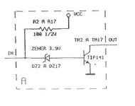
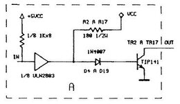
The revised (new) driver board has a slight re-design which should avoid this all being well... It was the "updated" driver board that was produced for Verne's World (the following release). As far as i can tell it's identical on the i/p and o/p and pinouts.....
Original board

Updated board

I would replace with square pin and tri-furcon terminals. Round pin against a flat terminal = minimal contact area. Tri furcon against a square pin = max contact area.
Thats true... I'll have to check out the type of socket that is on the other end a little closer... As far as I can see they are Molex KK series .156" square pin's on the other end, which if this is the case then i'll replace with the matching connectors on the other end - it seems like the best plan unless they are junk...
Thats true... I'll have to check out the type of socket that is on the other end a little closer... As far as I can see they are Molex KK series .156" square pin's on the other end, which if this is the case then i'll replace with the matching connectors on the other end - it seems like the best plan unless they are junk...
you could allways change the other connector to match ;0)
There's some odd stuff going on with several of the components. There are at least four different types of diodes. Why are they floating up so high, along with three of the TIP141s? And it looks as though they've been soldered from the top-side?
Yup that was the original board... It's the usual op trick of "rather than replace a component properly, lets snip off it's legs and solder it's replacement to the top side". Which they could have done on the top TIP141, if it wasn't for the fact there's a hole in the board and they bodged the solder job through it!!....There's some odd stuff going on with several of the components. There are at least four different types of diodes. Why are they floating up so high, along with three of the TIP141s? And it looks as though they've been soldered from the top-side?

Is this the same board you posted about recently but you were asking about the best way to populate a new board from scratch? After I posted I did think again about what was going on and then the penny dropped: it's a hack/fix that was done with the board in-situ. Must have been a total bitch to solder the parts with the board in the back of the cab - surely he would have been quicker and easier to pop it off and do it on a table? Sheesh...
Thats the board  (Well the better looking one!).
Op's.... Sheesh...
Op's.... Sheesh...

