What's new
Pinball info

Register a free account today to become a member! Once signed in, you'll be able to participate on this site by adding your own topics and posts, as well as connect with other members through your own private inbox!

VECTOR Transformer AS-3071-2/ES-122-14?

astyy

Play Flipper Games for Fun and Recreation
5Years
Joined
Jan 19, 2015
Messages
3,120
Location
Basingstoke
I'm cleaning up and testing the transformer I've sourced for my VECTOR project. Here's a photo and the markings now legible - AS-3071-2/E122-142.
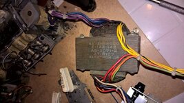
WP_20151014_09_14_15_Pro__highres.jpg

The VECTOR manual pg 27 lists the part as AS-3071-2, however on pinwiki there are two variants putting out different voltages on winding 4

upload_2015-10-14_10-14-38.png

This is mentioned on the VECTOR Power Supply Schematic showing either rectified to 6.5 Vdc for the Switched Lamps.

upload_2015-10-14_10-18-34.png

I'm interested to know which variant is right as the manual isn't clear and what other VECTOR Club owners have installed.

Thanks.
 
The way I read that is that they just installed whatever they had available sometimes it was 9.4 VAC other times it was 8.2 VAC. Both produce the same end result of 6.5 VDC...
 
I'll give you 3 guesses who updated PinWiki with that information? ;)

I added both variants because I noticed the different part numbers on the schematic you have highlighted. I have found mention that FLASH GORDON contained an E-122-141 but checking the manual it has the exact same schematic, W-1233b, as VECTOR.

In reality it makes little difference. The Vrms of 9.4 VAC is 6.65 and for 8.2 VAC it's 5.8, both acceptable for running the switched illumination. Given the choice I'd go for the E-122-142 as the slightly higher voltage is closer to the 6.3 volt rating on #555 lamps.

I've checked in my VECTOR but there are no discernible markings on the transformer. I also looked at the setup in PARAGON. It has a transformer with a 7.8 VAC winding and the switched illumination bus is stated as 5.4 VDC (Vrms works out at 5.52) even though the #47 lamps are rated at 6.3 V.

Why the change? Not sure. Maybe as later games got more switched lamps they slightly upped the voltage to reduce the current for switching on a given number of lamps.
 
Thanks both, that must be a generic schematic and I love the note that says 'See Game Manual of Specific Game for Correct Dash/Part Number' when it's in the game manual!

Anyway, it's defo right, wiring, continuity and resistance on both sides all look good, will connect up to mains later to (carefully) check the o/p voltages. Also it has no jumpers to set 240V which I need to attend to first.
 
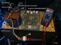
Test the transformer output voltages like this (notice the orange jumpers in plug J1):

farm6.staticflickr.com_5560_15104397048_369924469c_c.jpg

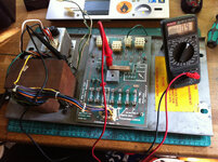
Then if that's ok connect J5 to the rectifier board and test the output voltages:

farm4.staticflickr.com_3862_15120305148_8d8b8d9ec5_c.jpg

Although not exactly the same the process is similar to what I did on GOLD BALL:

http://www.pinballinfo.com/communit...in-budget-restoration.14097/page-2#post-81701

Just double and triple check the orange input voltage jumpers for VECTOR as GOLD BALL has it's own unique transformer!

!!! AND IF YOU'RE ARSING AROUND WITH BARE ENDED MAINS CABLES MAKE SURE YOU'RE BEING EXTREMELY CAREFUL !!! I tend to wear thick gloves when doing this sort of stuff and switch off and unplug the mains between each test ;)
 
Well I followed @Nedreud test rig setup and have recorded good results from transformer outlet plugs and then from rectifier module TPs. I will start a shop log and record there.
 
neutral black and live white ..... isn't that the wrong way round?
It was only a temporary test rig cable. Black and white is old US colours and not legal in the UK. Now that this PSU module is back in GOLD BALL it has nice new blue, brown and green/yellow cable ;)
 
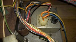
I'm missing the 12-pin plug that attaches the mains wiring (and voltage selection jumpers) to A2-J1, it is keyed on pins 1,3 and 11 - pic below from my GOLD BALL.

What plug is this and what size crimp pins are needed? Also I want to rewire the mains side so what gauge wire is the - blue & yellow shown?

WP_20150124_14_28_25_Pro__highres.jpg

Many thanks for helping.
 
I'd go for something like this: http://www.ebay.co.uk/itm//230975732833

Rated up to 1500 V and 10A @ 20°C / 6A @ 70°C. It's 32 strands of 0.2mm, so 1mm². Basically, it's one of the cores out of 10A 3-core mains cable.

CPC have it but can only find 100m rolls!

As for the connector I believe that they are MLX™ Power Connectors: http://www.molex.com/molex/products...Title=Introduction&parentKey=power_connectors

Checking the drawings (http://www.molex.com/pdm_docs/sd/050841120_sd.pdf) I think you need this one, part number 50-84-1120 (or 50-84-1125 which is white instead of clear plastic): http://www.molex.com/molex/products/datasheet.jsp?part=active/0050841120_CRIMP_HOUSINGS.xml. The drawing shows the keys on pins 2, 10 and 12 which I guess is the same as 1, 3 and 11 if you numbered the pins from the opposite end (if you look very closely at the connector you'll see tiny tiny numbers along the edges - you'll need an eyepiece probably!)

Could be a bugger to get though. None on eBay. CPC don't seem to have them. Farnell/Element14 have got the white ones code 50-84-1125 but only as US stock so £15.95 charge to deliver to the UK. Mouser and DigiKey both have them (and cheaper) but £12 delivery.

Pinball Mania might have them if this is the right item (http://www.pinballmania.co.uk/partslist.htm):

CNP-06-2122 Connector Plug 12 pin 3x4 0.062"
 
Thanks chaps, I'll post some pictures soon of the existing wiring arrangement for your amusement.
 
Back
Top Bottom