What's new
Pinball info

Register a free account today to become a member! Once signed in, you'll be able to participate on this site by adding your own topics and posts, as well as connect with other members through your own private inbox!

Understanding Micro Switches

Carl Spiby

Registered
10 Years
Joined
Feb 24, 2013
Messages
2,707
Location
Kendal, Cumbria
I'm struggling to understand the placement of the diode on a micro switch, it appears the normal way to wire it is to have the green ground wire on the NO leg, Switch pulse on the NC leg, then a diode bridging NC and Common with the banded side nearest the Common.

I have tried googling for the answer but I can't find an explanation that I can understand, I don't like doing things without knowing why, even if it is correct.

Furthermore, how do you wire a micro switch with 4 legs on?

Thanks
 
At rest the nc and common are closed shorting the diode, but doesn't matter because the green wire on NO is not connected - open.

When operated , the NO Goes closed. The NC goes open. The diode is now active and the banded end which is connected to the common is internally connected to the green wire on the NO tab which is currently closed. The other end of the diode is connected to the white wire.

I've never seen a four legged microswitch used in a pinball. Connect it exactly the same you would a three legged I guess and ignore the fourth.
 
Because then you get switch matrix confusion. Switch strobes can get routed via a diode short to the wrong column creating a ghost switch closure on a column which should not be active.
 
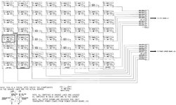
Carl, it might be easier understand from this drawing:

home.comcast.net__pfutz_Capcom_bulletin_switch_matrix_phantom_switches_1.jpg

But definitely read the link Andy posted too if you want to understand in more detail :)
 
It's certainly possible to have a delay on a switch physically, electronically (using a latch on a RC network) or in software.
 
Back
Top Bottom