What's new
Pinball info

Register a free account today to become a member! Once signed in, you'll be able to participate on this site by adding your own topics and posts, as well as connect with other members through your own private inbox!

Twilight Zone Switch Issue

Jonwolf

Registered
5Years
Joined
Apr 4, 2016
Messages
1,136
Location
Wolverhampton
Afternoon all,

My TZ test report tells me that a batch of switches are out. I've checked and the following switches:

Switch 31 - jet bumper
Switch 32 - jet bumper
Switch 33 - jet bumper
Switch 34 - slingshot
Switch 35 - slingshot

None of these are registering in switch test and also neither do the following left Outlane and inlane switches:

Switch 36
Switch 37
Switch 38

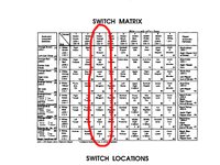
See pic below

I've checked fuses and LEDs on CPU which are fine.

Might there be a short under the playfield?
uploads.tapatalk_cdn.com_20160709_cd64ffdff732bb7944581c3be3458ed8.png.jpg


Sent from my iPad using Tapatalk
 
Already done that Grizz - even swapped it to J107 which apparently is same connection. No joy


Sent from my iPad using Tapatalk
 
Visual check of switches appears ok - loose or touching wires/tabs on any switches. I'll look again though


Sent from my iPad using Tapatalk
 

  • Could be U20 has failed. Check the switch column using this method ...(taken from the Bible ..... :))


    Testing the Switch Columns (all WPC revisions).

    To test the switch columns, do the following:
    1. Remove the backglass and fold down the display to gain access to the CPU board.
    2. Turn the game on.
    3. After the game boots, press the "Begin Test" button in the front door. Go to the Test menu's "Switch Levels" test.
    4. Unplug the connectors at J212, J206, J207, J208 and J209 (lower portion of the CPU board).
    5. Connect an alligator test lead to pin 1 of J209. Pin 1 is the right most pin, as facing the board.
    6. On the other end of the alligator test lead, clip on a 1N4004 diode, with the banded end away from the alligator lead. Touch the banded end of the diode to pin 1 of J207. Again, pin 1 is the right most pin, as facing the board.
    7. The display should show switch 11 is closed.
    8. Move the diode/alligator lead on J207 to the next pin. The display should show switch 21 is closed.
    9. Repeat the previous step, until pin 9 of J207. Switches 11, 21, 31, 41, 51, 61, 71, 81 should be closed on the display as moving forward, pin by pin, on connector J207.
      Note: on some WPC games, columns 8 and/or 7 are not used. In these cases, there may be no indicator for switches 81 and/or 71.
    If a particular column does not display as closed, or is closed without any test lead connection, replace the ULN2803 at U20 on the CPU board.
 
Thank you Grizz - this shall be be done tomorrow. I am currently a bit ****ed so it's best to do it with a hangover tomorrow ;-)


Sent from my iPad using Tapatalk
 
Just read the post properly. I got lost at step six. I have a wire with croc clips but the diode is the bit on the switch that is soldered on and looks a bit like a resistor?


Sent from my iPad using Tapatalk
 
Yes, usually black with a white painted band at one end. If one of the diodes on the row or column of a switch matrix is faulty / soldered to the wrong terminals of the switch/ soldered the wrong way round - it can give multiple switch errors

The good news is that if you find it, all your multiple problems can be cured with one fix

I had all sorts of madness when i got my funhouse as a bad repair had been done and one diode was soldered incorrectly to one switch
 
Just read the post properly. I got lost at step six. I have a wire with croc clips but the diode is the bit on the switch that is soldered on and looks a bit like a resistor?

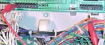
I've used this method before. You need an extra diode that you clip to the end of the croc lead and use as a probe. Not the exact setup but like where it says 'Band' below.

techniek.flipperwinkel.nl_desega_desw4.jpg
 
Thanks guys, that's really useful. I need a diode now - anyone got a spare or where/what part number do I get one ?


Sent from my iPad using Tapatalk
 
Thanks - is this test lead arrangement the same as what is identified in the advice in the pic ?
uploads.tapatalk_cdn.com_20160710_f94b256661c84e2241f623572b7046cb.png.jpg


Sent from my iPad using Tapatalk
 
Andy has been helpful and said it didn't need a diode in the test lead, just use a lead.

I disconnected J212, J206 and J208 and went into switch edge test.
When connecting J206 -1 in sequence to the pins on J208 the switches register.
Same for J206-2 - all good.
When I connect J206-3 to any of the pins on J208 there is nothing. Makes sense as the column in the switch matrix uses J206-3.
As J206-3 is not registering with connectors J212,J206 and J208 all isolated from the playfield this must mean that the issue is on the CPU board?
Can anyone confirm this diagnosis so I can send it off for repair.

Thanks


Sent from my iPad using Tapatalk
 
Back
Top Bottom