Hi,
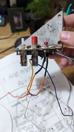
Is the problem the wiring at the switches themselves? It would be the same as any System 11 game, regardless of the type of door, as below.
Some late system 11 games did have a sentinel/220 door factory fitted; I've seen a Rollergames with one, though the u.k. spec didn't have this for Williams-branded games until the very last game, Riverboat Gambler. That circuit board provides 12v power for an electronic acceptor, but there were still only three coin inputs, so factory fitment acceptors weren't programmed for 20 pence, and the entry label omitted 20 pence. The electronic acceptor details were shown in a separate supplement, which I suppose you don't have to hand.
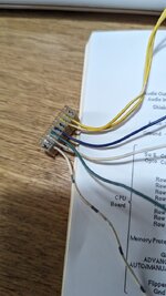
There are really only two service switches for System 11, though, using three wires* in a dedicated connector on the Cpu board; they've no connection to the switch matrix. I think it's 1J14 that's used, a 4-pin header with one pin blank. One wire is ground, pressing Advance connects the line which signals the program to enter test to the Ground wire. Which entry point is used (tests or direct to auditing/adjustment) depends on whether the third wire is grounded or not; the central 'Up/Down, Manual/Automatic' switch latches into the closed position to make/break the ground connection. The Cabinet Wiring diagram usually shows the two switches and wire colours.
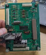
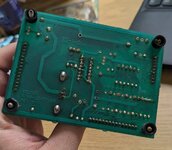
*The three of them are shown in the diagram visible in your second picture; GND, Advance, Auto/Manual. As I recall, they're Black, White and Blue. It would be common to any System 11 game, and quite possibly earlier, too. The interface board isn't going to do anything with them, only route them through for tidiness (originally, anyway).
I've now looked at ipdb - the Transporter paperwork there shows the switch wiring in the cabinet diagram. I was wrong about Black; it's White for Ground (common to both switches), Green for Advance (so Green to White goes into tests), and Blue for Auto/Manual (connected to Ground for Auto/Up function). And 1J14 does have all four wires in, as the Memory Protect switch operated by the door uses it too (Black-red connecting to Ground).
So looking at what remains, that may be the original White ground wire, looped to both switches. Then that Blue wire may be right, so you need to find Green and arrange to connect it to White to get into tests. You may be best discarding that old-type Bally switch and transferring the unused 3rd switch (if it works) to become the Advance switch. I once had a home-made alternative control box, with the two switches from an broken-up game in a plastic box, and the wiring to the connecting header. With this connected to 1J14 instead of a games own wiring, I didn't need to reach over to the door to enter and operate the tests if I was checking components in the backbox.
As for the switch pins, each switch has two separate circuits or 'poles', with three pins each. Going by the central switch (the only one even close to original), the centre pin(s) are Common, connected to the upper or lower pin according to the position of the push button (a 'changeover' switch). So attach the White ground wire to a centre pin of both switches. Leave Blue as it is, hopefully it's right. Use a meter on continuity/buzzer to find which of the upper/lower pins connects to centre when the Advance button's pressed, and attach Green to this.


