What's new
Pinball info

Register a free account today to become a member! Once signed in, you'll be able to participate on this site by adding your own topics and posts, as well as connect with other members through your own private inbox!

Tiltaudio sound board and SMS build

Kenpuk

Site Supporter
Joined
Mar 3, 2025
Messages
36
Location
Bramley
Hi all,

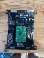
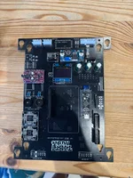
Has anyone had experience of building and installing the Tiltaudio sound board and SMS? After much ado I managed to finally complete the Serial Media Server build but had to use an early era RPI3B as the image would not run on anything older than a 2019 board. Now I have issues with the sound board, I’m able to play sound via the UI commands but it isn’t triggering via the CPU (so no game play sound). I suspect the issue is with the STM32 daughter board but don’t seem to be getting anywhere fast at the moment! Any thoughts would be great appreciated 👍
BTW it’s for the Hologram replacement on a CFTBL 👍
 
Built one years ago.

Post pictures of your boards please.
 
Built one years ago.

Post pictures of your boards

Built one years ago.

Post pictures of your boards please.
On boot, the STM32 LED indicators both come on (red & blue) blue goes off and does not flash when there is activity on the game! The 12v and 5v rails are both present and stable. The ribbon cable from the CPU is oriented correctly also.
Thanks for taking a look 👍
Ken
 

Attachments

  • IMG_2158.webp
    IMG_2158.webp
    166.9 KB · Views: 17
  • IMG_2156.webp
    IMG_2156.webp
    172.5 KB · Views: 16
Can you get closer to them at all - it's blurred when I zoom in?
 
Check your stm is flashed. You can do this by checking the log file on the sd card. Post it here if you not sure.
 
Check your stm is flashed. You can do this by checking the log file on the sd card. Post it here if you not sure.
Thanks for the heads up, I’m out all day tomorrow but will check tomorrow evening and share the log file 👍
 
Check your stm is flashed. You can do this by checking the log file on the sd card. Post it here if you not sure.
Hi bud,

Yes there is a problem with the STM32, flash failed at boot, have tried to force unlock and erase in order to reload stm-firmware-0.2.bin, however protection persists no what I try!
 
OK. I normally just rewrite the sd as it tries to flash on first boot but if it's not flashed there are 2 things it could be.
1 - bad solder or connection. Hope its this. Get your multimeter out and check continuity between the stm and pi. Looking at your photos I'd start with the 4 pins at the bottom of the stm. You used the 90 degree pins for some reason so it's a little odd. The middle 2 pins are essential for the pi to see the stm. Wiring diagram to help check continuity.024f643298fe45fd94fbf0aabd9133a6-1.webp

2 - bad stm board. Unfortunately it can happen. If you're really really sure it's not your soldering I mean really then replace the stm. Not easy even with a desoldering gun.
 
Thanks for the great advice, I’ve been through all the connections and all look good with full continuity. I was never happy with the build instructions that came with the board. The STM32 came with the 4 pin rail fitted with a rear straight connector instead of below the board for direct connection to the pcb, this was a mod to the original with addendum instructions!
At the moment the STM32 seems to be stuck at level 1 so I’ve ordered a stlink v6 to enable reset to level0 and mass erase directly and if all is good it should flash when booted. That arrives today, I did toy with desoldering the board and fitting sockets to mount a replacement but thought I’d try the STlink first.
 
Glad your connections are good. In which case it must be the stm board so I think your doing the right thing. I have never done the stlink but I know others have had success using this method. And is way better than removing a component soldered directly to the board.

I bought some stm boards, amps and screens separately so I can always change them out if I have problems using the socket method.
That makes so much sense using sockets and I should have waited and ordered them. I’ll,let you know how I get on with STlink v3 as I’ve never done before either 😃old dogs new tricks I believe the phrase is 🤣
 
Glad your connections are good. In which case it must be the stm board so I think your doing the right thing. I have never done the stlink but I know others have had success using this method. And is way better than removing a component soldered directly to the board.

I bought some stm boards, amps and screens separately so I can always change them out if I have problems using the socket method.
Hi buddy,
I received the STlink this afternoon and used cube programmer to interrogate the STM32, it was write protected and firmware corrupt. I set it for unprotected and flashed a copy of the Tiltaudio firmware on. When reinstalled the game play audio came up and it sounded great😃
Now just working integrating the serial media server.
Thanks for your advice and I’ll let you know how I get on with the full holo replacement.
Cheers
Ken
 
Maybe I should have tried the stlink but I guess end result is a stm that is flashed is a win.
Pleased it worked for you 👍
 
Back
Top Bottom