Hi all
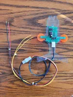
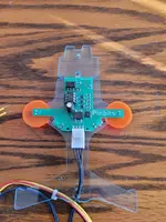
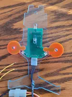
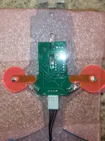
I've just finished installing my Ultimate Hunter Killer mod by avo-pinball.de.
I believe this is the same HK mod that Ant put on his restored T2.
When I bought my pin, the basic standard plastic HK wasn't included. It wasn't a big miss, as it was quite cheap looking.
However, I'm a stickler for accuracy to Stan Winston's designs and it came down to this and another HK mod.
The other HK mod looked more detailed but it didn't move like this one does.
This one scans the playfield in skill shot/multiball/jackpot modes and shakes back and forth if you successfully hit your shot.
It's a really nice addition and I'd recommend it. It is a bit pricey when you factor in shipping as well as post-Brexit customs charges - came to £353 in the end but I really think it adds another element to a great game.
The instructions are HERE. They are translated from German so there's a bit weird English in places but it gets you there.
The hardest bit was locating the tiny 5mm screws in the extremely small holes on the bracket. This took me ages.