Am quite new to this title and giving it some love. One of the things I loved about the System 11s was the fantastic flash bulbs (especially f14 tomcat) - but they are crap in my game!!!!
The individual flasher circuits on this game often have 3 or 4 bulbs in. I am using incandescents.
The different circuits have radically different brightness, and I have not seen this in a game before.
Does anyone know why this might be ?
4 bulb circuits ....
Right seems a bit weak
Relaunch is far too weak
Flame Flasher is absolutely pathetic
Removing 1 bulb from Flame Flasher helps, but you need to remove 2 to get the remaining ones properly bright
3 bulb circuits ....
Top Flasher is really bright, as I would expect
Left Flasher is OK, but nowhere near as good as the Top Flasher
Does anyone have any ideas what this might be pls ?
I can see that a previous owner has replaced the relevant Bridge Rectifier on the 50v circuit - I put a new one in myself.
Testing the volts to the flashers it seems to be about 38v. It is about the same on my Whirlwind and Transporter which use the same boards.
But as some flasher circuits are fine that suggests that voltage is not the problem.
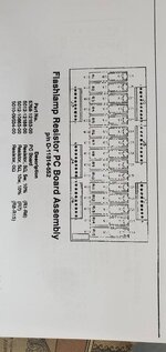
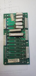
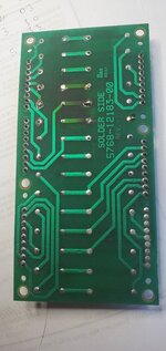
Is this just a case of reflowing solder on the pins, new connector, clean bulb connectors, the bulb holders ?
Or might the power transistors that drive the flashers be failing? Or the drive transistors failing ?
Any suggestions very gratefully received
Thanks


