Pinball info
You are using an out of date browser. It may not display this or other websites correctly.
You should upgrade or use an alternative browser.
You should upgrade or use an alternative browser.
Sys11 Coil locked on, lots of coils not working
- Thread starter David_Vi
- Start date
Q1 on aux power board is dead also. @myPinballs is sending me some bits so I can have a bash at that
@Lecari bought me the Zaccaria Locomotion that was on here a few weeks back as a surprise... It turns up and is left on doorstep because it doesn't fit through the door.

I'm scared to set it up, might leave it a while.


Yes and it continues...@David_Vi you are perhaps the unluckiest pinball owner at the moment.
@Lecari bought me the Zaccaria Locomotion that was on here a few weeks back as a surprise... It turns up and is left on doorstep because it doesn't fit through the door.
I'm scared to set it up, might leave it a while.
- Joined
- Jul 21, 2011
- Messages
- 2,527
From what i can see on the video, the group of coils 1,2,5,and 8 on both A side and C-side dont work. The common item to these 8 things is the 25V supply. Use your meter to measure for 25V DC at both sides of the fuse at Fuse 2. If absent, check Fuse 8, which is the AC fuse prior to the bridge rectifier. Measure on an AC scale with probes between J8-3 and both sides of fuse F8.
If you get a different voltage on opposite ends of fuse, then that fuse is bad.
None of this should have a bearing on the locked on coil/flashers. I think this might be a secondary issue
If you get a different voltage on opposite ends of fuse, then that fuse is bad.
None of this should have a bearing on the locked on coil/flashers. I think this might be a secondary issue
I'm going to replace Q1 and whatever transistor is on the mpu (since forgotten but I know it tested dead).From what i can see on the video, the group of coils 1,2,5,and 8 on both A side and C-side dont work. The common item to these 8 things is the 25V supply. Use your meter to measure for 25V DC at both sides of the fuse at Fuse 2. If absent, check Fuse 8, which is the AC fuse prior to the bridge rectifier. Measure on an AC scale with probes between J8-3 and both sides of fuse F8.
If you get a different voltage on opposite ends of fuse, then that fuse is bad.
None of this should have a bearing on the locked on coil/flashers. I think this might be a secondary issue
Will try that voltage too thanks.
From what i can see on the video, the group of coils 1,2,5,and 8 on both A side and C-side dont work. The common item to these 8 things is the 25V supply. Use your meter to measure for 25V DC at both sides of the fuse at Fuse 2. If absent, check Fuse 8, which is the AC fuse prior to the bridge rectifier. Measure on an AC scale with probes between J8-3 and both sides of fuse F8.
If you get a different voltage on opposite ends of fuse, then that fuse is bad.
None of this should have a bearing on the locked on coil/flashers. I think this might be a secondary issue
I put one lead to gnd and second on either side of the fuses, is that right?
You might have to explain like I've never used s multimeter because in an earlier thread I said I was measuring voltage by putting one probe on gnd and using the other to test voltage.
I realized this doesn't apply to every situation.
If I do that with F2A I get a DC value that jumps around and never settles
F2C Does same but much much higher values.
F8 reads 18v but fluctuates past the decimal point but sticks to 18v
Both sides of fuses showed similar results
For power measurements on the fuses, use the DC voltage measurement and you can use any of the board mounting screws (to the cabinet) as a ground. Then you should get a 25V DC measurement (use 0-100V or whatever your nearest range is) on either of those fuses. FOr F8 (which is on the AC side coming up from the transformer, set your meter AC V and again you can measure fuse to backboard ground.
You should get a solid 25V from the output side of either of the F2s. Anything else is either a meter ranging problem, or a power supply problem. Start there first, Then you can track down the driver fault that caused the coil to lock on once you hvae stable DC power for the 25V circuits.
Hope that helps.
Does help!For power measurements on the fuses, use the DC voltage measurement and you can use any of the board mounting screws (to the cabinet) as a ground. Then you should get a 25V DC measurement (use 0-100V or whatever your nearest range is) on either of those fuses. FOr F8 (which is on the AC side coming up from the transformer, set your meter AC V and again you can measure fuse to backboard ground.
You should get a solid 25V from the output side of either of the F2s. Anything else is either a meter ranging problem, or a power supply problem. Start there first, Then you can track down the driver fault that caused the coil to lock on once you hvae stable DC power for the 25V circuits.
Hope that helps.
I struggle understanding how to measure voltage. I was taught how to test boards via test points and somehow kept using that technique for everything
So this works for seeing what's going through a fuse or tp but not for something that isn't bridged like a lamp holder or GI string?
For the fuse test I posted about earlier I did do it the way you're suggesting, but it didn't give 25v.
I don't know what is meant by meter range.
This is my multimeter (picture from locomotion, testing incorrectly but ignore that)
Its a basic one I got when I first got my pins so not sure if it's any good!

Hi, David,
Meter Range is the scope or limit of the measurement selected. For example, 10v DC means that the maximum reading on that range (sending the needle to full scale on an analogue meter) would be 10 volts DC.
Has the meter got a continuity test, where touching the probes together sounds a buzzer? With a fuse removed from the clips, it should sound the same if it's alright, as a fuse doesn't have much, if any, resistance.
Hi, David,
Meter Range is the scope or limit of the measurement selected. For example, 10v DC means that the maximum reading on that range (sending the needle to full scale on an analogue meter) would be 10 volts DC.
Has the meter got a continuity test, where touching the probes together sounds a buzzer? With a fuse removed from the clips, it should sound the same if it's alright, as a fuse doesn't have much, if any, resistance.
Yup continuity test is my favourite as I understand it and can use it

AC and DC voltage I am getting there...
Mines digital so I suppose it doesn't need to have a range setting?
As far as I know the fuses tested good. Tomorrow is the day to have a further dig into BK, I also have a few transistors to replace the bad ones on aux and mpu board.
But as @Ruaraidh says I should find out if the power is ok first
I think quite a lot of digital meters have auto-ranging, though I prefer analogue myself.
To see if non-working coils are powered, I'd measure working ones first, on dc voltage, to see what to expect. Bearing in mind that System 11 games have a mixture of 25v and 50v coils. Though on Black Knight 2000, I'm not sure if there is anything besides the outhole, feeder and eject on the 25v side. Maybe the jet bumpers, as it's the final game with 'special' drives for them. Or the illumination breaker relays, or solenoid A/C relay. If the affected coils aren't powered, check through the circuit pathway, i.e. the pins of the Aux Power and Interconnect boards, etc, where the missing power feed passes
To see if non-working coils are powered, I'd measure working ones first, on dc voltage, to see what to expect. Bearing in mind that System 11 games have a mixture of 25v and 50v coils. Though on Black Knight 2000, I'm not sure if there is anything besides the outhole, feeder and eject on the 25v side. Maybe the jet bumpers, as it's the final game with 'special' drives for them. Or the illumination breaker relays, or solenoid A/C relay. If the affected coils aren't powered, check through the circuit pathway, i.e. the pins of the Aux Power and Interconnect boards, etc, where the missing power feed passes
Last edited:
Going by the schematic, fuse 2A protects 25v solenoids on the 'A' side of the extender relay, so that would account for them not working. Differing from fuse 1(and maybe 3*), fuse 2A connects through the extender relay. There usually isn't a fuse 2 as such, but 'W6' is fitted instead, this trace is the input for 25v into the relay. I wonder if the relay contacts may be damaged, or its connection to the circuit board is breaking. If there's a good 25v at W6, then with the relay off it should appear at fuse 2A, and with the relay on it should change to fuse 2C. Or, with the machine switched off, there should be continuity between W6 and fuse 2A, but not fuse 2C.
* fuse 3 can be used for either voltage, depending on how the board is jumpered with 'W' links. W4 for 25v, W5 for 50v. As far as I can tell, for BK 2000 it should be W1,3,4 and 6.
* fuse 3 can be used for either voltage, depending on how the board is jumpered with 'W' links. W4 for 25v, W5 for 50v. As far as I can tell, for BK 2000 it should be W1,3,4 and 6.
Last edited:
Going by the schematic, fuse 2A protects 25v solenoids on the 'A' side of the extender relay, so that would account for them not working. Differing from fuse 1(and maybe 3*), fuse 2A connects through the extender relay. There usually isn't a fuse 2 as such, but 'W6' is fitted instead, this trace is the input for 25v into the relay. I wonder if the relay contacts may be damaged. If there's a good 25v at W6, then with the relay off it should appear at fuse 2A, and with the relay on it should change to fuse 2C. Or, with the machine switched off, there should be continuity between W6 and fuse 2A, but not fuse 2C.
* fuse 3 can be used for either voltage, depending on how the board is jumpered with 'W' links. W4 for 25v, W5 for 50v


I haven't got a physical manual or schematics, I feel it would make understanding this a bit easier.
Trawling the pdf version is tricky, where is W6?
Could you give me a pointer or at least the page of the operations manual?
The ipdb.org manual listing for BK 2000 doesn't have the schematics, so I looked at the one for Earthshaker, which is similar. Page 84. W6 is a tiny white resistor-like jumper, above the extender relay, K1. It looks especially puny, located inside a screened white outline marked F 2. Below a stack of four large third-stage TIP36 transistors.
Last edited:
Definitely having either the pdf or physical manual for the pin will make this kind of fault finding much easier. The Williams manuals and schematics really are very good and make digging out these kind of problems much easier!
Ok few readings, no idea what to make of them.
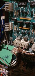
On aux power driver board
W6 Both sides = 40v DC (seems high?)
F8 both sides = 18v DC
J8-3 = 18v
I've got transistors for Q1 and Q32,
Should I swap them in or is there something I should check regarding the voltages above first?
On aux power driver board
W6 Both sides = 40v DC (seems high?)
F8 both sides = 18v DC
J8-3 = 18v
I've got transistors for Q1 and Q32,
Should I swap them in or is there something I should check regarding the voltages above first?
Replaced Q1, Q29, q33 and q34.
Turned on, had a weird buzz. So turned off.
Tried again and no buzz. In test same result.
But now left kickback goes off twice, one in its test and then on magnasave test.
Then noticed Q14 is gone.
Q32 broke off when I moved it slightly to help solder Q33 so I assume Q14 broke off when I was soldering also, really annoyed I didn't check or notice.
A few of those transistors test bad now, with 1.400 one way and 0.500 the other in diode test.
Including Q32, Q30, Q15
On aux power board
Q1 (which I replaced), reads 1.400 and 0.500 the other way round.
As does Q7 Q2 and Q3.
In diode test they're supposed to read 0.500 ish one way and 0 the other right?
I compared with Diner's and they read same so I suppose those ones are different...
Still the mpu ones...why?
I took the board out again to put Q14 back. I found it and it tested good so I thought I'd try solder it back, at least for testing purposes.
I thought I'd test the other TIP transistors again, and now they're all showing as good. I dunno why they weren't testing right in the machine but it seems that bottom row is all good.
Good news is magnasave and kickkback are behaving. stuck coil and flashers are solved!
But still 3 coils not firing, outhole, ball serve and right eject.
Attachments
Last edited:
Those few coils weren't getting power.
Traced it to F2A and tried to follow it further then got confused.
I thought to eliminate the aux driver board I'd swap the one from Diner in.
Then everything worked!
So it's something on the aux driver board.
What I do know is F2C gets power.
And what I understand is power between F2A and F2C comes via a relay which decides whether to power F2A or F2C
The relay clicks so it must be working?
What next?
Also that horrible noise happens sometimes when turning on and doesn't go away until you turn off. Any ideas what that is?
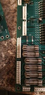
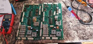
Ok I think I have it!
Got both diner and bks aux power driver boards in front of me.
Continuity test so I could compare.
On working board there's continuity from D23 to F2A
Not on bk2k's board
Seems to be the relay.
I can cut continuity on the working board by pushing the relay.
Unfortunately bks relay has a cover over it I can't seem to get off.
Attachments
Last edited:
Are any of the solder connections for the relay cracked? D23 is the tie-back diode for the winding of the relay - it is on the 25v rail, if not the actual power feed to the 25v contacts.
Are any of the solder connections for the relay cracked? D23 is the tie-back diode for the winding of the relay - it is on the 25v rail, if not the actual power feed to the 25v contacts.
Trying to compare now. They both have continuity.
The diodes measure differently though
Working board D23 and D12 0.300(ish) both ways
Non worker D23 D12 0.500 and 0
I thought Working diodes were supposed to be 0 on one end. I'd assume the working board is the failed one but what do I know.
Are they the same type as you use on coils?
Attachments
This is where they've been moved to, when Williams decided to take them off the playfield. The smaller diodes on that board are similar to those previously used on coils, '4003' rather than (as I recall) '4004'. Their reverse-voltage rating is a bit lower, i.e. the voltage they can face up to before breaking down. But the ones linked to the 3rd stage transistors for 50v coils are the same, so they're up to it. A diode only conducts in one direction, so using a continuity tester or ohm-meter, one way should be quite a low resistance, and the other a very high resistance, effectively an open-circuit. Though other components in the circuit when the diode's in a board, or across a coils' terminals, can affect the readings. But adopting the banded end of D23 as the 25v 'rail', there should be continuity between cathode (banded end) of D23 (or Fuse 1, 3, or W6/'Fuse 2') and Fuse 2A, with the board not powered, as it's out of the machine. If the board has the relay pins marked, the 25v input to the contacts is pin 5, and the 'A' side output is pin 1.
Last edited:
D23 is across the relay coil - if on the non working board you are getting a 0 reading one way then I'd suggest the relay coil is broken, ie. open circuit. However you seem to think you've seen it working? Do a solenoid test and verify it is working, you should see the contacts move if it is.Trying to compare now. They both have continuity.
The diodes measure differently though
Working board D23 and D12 0.300(ish) both ways
Non worker D23 D12 0.500 and 0
I thought Working diodes were supposed to be 0 on one end. I'd assume the working board is the failed one but what do I know.
Are they the same type as you use on coils?
One the working board I would expect the reading you got because you are not actually testing the diode, you are instead effectively testing the relay coil. so it will be the same reading both ways.
David, you didn;t answer Jay's question - are the relay connector pins cracked. This is what you are looking for in extreme. Even hairline cracks can stop continuity. Reflowing cracked joints could be the simple fix.Are any of the solder connections for the relay cracked? D23 is the tie-back diode for the winding of the relay - it is on the 25v rail, if not the actual power feed to the 25v contacts.
Paul

Above photo was a cracked solder joint on a GI connector.
Not cracked, I checked using continuity test on the DMM.
The relay definitely worked before as you'd hear it click in the test. You can hear it in the video I did originally. But A side wasn't getting power.
In coil test it does nothing
Im so drained and Bk had Diners board in it for now, so I've been cleaning it up and checking bulbs etc.
Are the diodes the same as you get on coils and switches? I think I have two spare somewhere if so.
If they're the most likely culprits I could change them .
If there's anything I can do to test it without it being in the game I'll give it a go. Just don't want to be leaning between pins the rest of today
Last edited:
Lowest rated diodes are 1n4001 and highest rated are 1n4007. You can go up not down if you don't have exact partNot cracked, I checked using continuity test on the DMM.
The relay definitely worked before as you'd hear it click in the test. You can hear it in the video I did originally. But A side wasn't getting power.
In coil test it does nothing
Im so drained and Bk had Diners board in it for now, so I've been cleaning it up and checking bulbs etc.
Are the diodes the same as you get on coils and switches? I think I have two spare somewhere if so.
If they're the most likely culprits I could change them .
If there's anything I can do to test it without it being in the game I'll give it a go. Just don't want to be leaning between pins the rest of today
The relay doesn't need to operate to supply power to the 'A' side; it's used to switch over to the 'C' side when required. If it's now stopped working at all, then the 'A' side loads (both 25v and 50v) would each be pulsed twice as the solenoid test progressed, The relay operates for its own sake as solenoid 12 in the test, without any of the sixteen possible loads being driven. I think BL/Knight 2000 actually has an "A/C switch test" which verifies if the relay is working.
With this circuit board, the 25v ('A') pathway is '+' of the 25v bridge rectifier BR1, W6 jumper, relay pin 5, relay pin 1, Fuse 2A, connector pins J11, No.s 4 & 5. All with the relay off. With the relay on, the final items change to relay pin 3, feeding fuse 2C, J11, 1 & 2. Since we've seen the 'C' side flashbulbs working, the circuit seems okay into the relay, but isn't reaching the 'A' side. I was hoping to find a broken solder connection where the relay connects to the circuit board, specifically Pin 1, the 'A' side output.
With this circuit board, the 25v ('A') pathway is '+' of the 25v bridge rectifier BR1, W6 jumper, relay pin 5, relay pin 1, Fuse 2A, connector pins J11, No.s 4 & 5. All with the relay off. With the relay on, the final items change to relay pin 3, feeding fuse 2C, J11, 1 & 2. Since we've seen the 'C' side flashbulbs working, the circuit seems okay into the relay, but isn't reaching the 'A' side. I was hoping to find a broken solder connection where the relay connects to the circuit board, specifically Pin 1, the 'A' side output.
The relay doesn't need to operate to supply power to the 'A' side; it's used to switch over to the 'C' side when required. If it's now stopped working at all, then the 'A' side loads (both 25v and 50v) would each be pulsed twice as the solenoid test progressed, The relay operates for its own sake as solenoid 12 in the test, without any of the sixteen possible loads being driven. I think BL/Knight 2000 actually has an "A/C switch test" which verifies if the relay is working.
With this circuit board, the 25v ('A') pathway is '+' of the 25v bridge rectifier BR1, W6 jumper, relay pin 5, relay pin 1, Fuse 2A, connector pins J11, No.s 4 & 5. All with the relay off. With the relay on, the final items change to relay pin 3, feeding fuse 2C, J11, 1 & 2. Since we've seen the 'C' side flashbulbs working, the circuit seems okay into the relay, but isn't reaching the 'A' side. I was hoping to find a broken solder connection where the relay connects to the circuit board, specifically Pin 1, the 'A' side output.
There's a lot going on here I'm not understanding.
To be clear, A now works C doesn't.
Plus C doesn't pulse twice like you'd think.
Relay doesn't operate in relay test either.
Before I fixed the stuck coil and cleaned the relay contacts only C side was working, Outhole, ball serve and right eject of A weren't working.
The last thing I did before C or relay not working was cut the relay cover off and make sure the A side contacts were making contact, that seemed to fix it but in the process something damaged the relay.
I used a multimeter with ohms test and the relay coil gave a reading that was a bit different to the working coil on the other board .
Something I'd like to understand (you may have to explain like I'm 5) is why if I push the relay closed, I get the voltage to F2C but nothing happens (I do have it repeating a C Side flash test). Is there something else that makes the C side work, like it knows if the relay isn't actually working?
Confuses me a lot