What's new
Pinball info

Register a free account today to become a member! Once signed in, you'll be able to participate on this site by adding your own topics and posts, as well as connect with other members through your own private inbox!

STTNG - Push here to work...

  • Thread starter Thread starter Wizbiscuit
  • Start date Start date
W

Wizbiscuit

My STTNG has developed a rather odd fault...

When I turn it on about 75% of the time it does not work.

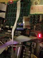
The led have have show on the picture is off (and another board to the left had side), so the power does not seem to be getting to the boards...

2016-03-08 14.30.57.jpg

Now if I give it a nice push around this area...

2016-03-08 14.31.14.jpg

The non-lit led pop on and the machine dances into life...

Now its a little hit-n-miss and often if I just push the connector at J105 it starts up, the odd thing though is I can actually disconnect J105 and the pin still runs, so it doesnt actually seem to be connected to J105... maybe the pressure is bending the board and fixing whatever connection is bad??? even when its working you hear that very slight sizzle sound that sounds like something being "just" connected...

The connectors just below this I can see are power, and I have re-crimped everything I can see, even put some new solder behind these connections to remove dry joints (though I am slighty guessing at this point)...

Before I continue on, any idea's what could be causing this??? oddly also is after the machines on, I can wiggle the cables and push connectors and it dont turn it off or reset it?? I would expect a loose connection would work both ways??

Got me flummoxed...
 

Attachments

  • 2016-03-08 14.30.57.jpg
    2016-03-08 14.30.57.jpg
    134.1 KB · Views: 25
Mmm manual seems to state that J105 is now connected, looks like that should be in J104...

J104·1
White-Blue,
50VAC,
to
Fliptronic
II
Board
J901-3
J104-2
White-Blue,
50VAC,
to
Fliptronic
II
Board
J901-1

Odd it works like this then... I will switch that over...
 
Have the bridge rectifiers been previously replaced? Suspect poor connectivity component side.
 
So far since moving the connector incorrectly in J105 to its correct spot of J104 it seems to be happy... everything is working, each time I have turned it on, its worked no issue...

If it happens again though I will check this bridge rectifier...

Fingers crossed...
 
Bugger, still doing it... bridge rectifiers here I come... I assume we are talking about a re-solder or replace??
 
OK, watched this Video...

Checked voltages as test 1,2,3,6,7,8...

Test2 has zero volts... when the pin works it has 5Vs, all the others are as expected...

So now I need to find what Test2 proves and what I have to change to possibly fix this... I guess one of the big fat capacitors and a rectifier?
 
I have no idea? should I drop some new solder on them? is each test voltage connected to a different rectifier? how do I know what rectifier to check??
 
Full schematics for the boardset are available here (among numerous other places on the internet) and tells you pretty much everything you need to know: http://mirror2.ipdb.org/files/1000/...ed_II_WPC_Schematics_Revised_May_17_1993_.pdf

Additional helpful information is available here: http://techniek.flipperwinkel.nl/wpc/index2.htm#reset

Have you taken the board out of the game and given it a thorough inspection for cold joints and poor connectivity around the bridge rectifiers as recommended by Andy @pinballmania?

To be brutally honest (and please don't take offence because that isn't my intention at all), it does concern me when these kind of questions are asked and there is so much information available online about how to troubleshoot and make a repair. Have you ever tried to repair a board before?

I bought my first pinball machine a little over 2 years ago and since then sucessfully repaired many faulty boards, in some cases fairly extensive surgery has been required to fix damage caused by previous battery leakage and a subsequent poor repair. Before this I hadn't ever seen the inside of pinball machine let alone worked on one, but I've never had to ask a question yet simply because everything you need to know is already out there if you look for it. It's not my trade but I have been interested in electronics my whole life and been using soldering irons and such like since a young boy. Before starting every repair I was therefore confident I could do a good job of it without causing further damage to the machine or myself.

That isn't to dissuade you from trying to repair your machine or asking questions about how to do so, after all that is one of the main purposes of forums like this one. In your case it sounds like it should be a pretty simple fix, most likely you need to find the poor joint/s and reflow them with solder to restore continuity. Just be aware that the risk of further damage to your machine and even yourself is very real if you're not careful, particularly when probing live circuits. If your probe slips and you short something out to the wrong place then you will blow stuff up, and yes I have done this myself! The voltages present in the areas you will be working on are sufficient to kill you so take it easy. :thumbs:
 
Look under the two bridge rectifiers. There are some tracks that should be joined to the wires with volcano shaped solder joints. If there dark rings around the wires of the rectifiers, then there will be poor connectivity. You can do your pushing test by twisting the heat sink backwards and forwards to see if the lack of 5v is associated with the bridges.
 
@aaronhicksuk i think you are the exception to the norm though, i had owned several before i attempted my first ever 'fix' (probably replacing a fuse or tinkering with a switch) and dozens more over a few years before i did my first transistor replacement. i was over 5 years in before i was replacing a bridge rectifier or trying to locate, let alone replace, a diode or a capacitor. you seem to have been born able to work with circuitry, so you're now pretty much my go-to guy for when i need my hand held to walk through a fix (and i really really appreciate that btw).

let's be honest, Wizbiscuit is pretty brave already with his multimeter and soldering iron. like the rest of us, he will cause a few ****-ups along the way, fry a few chips and get a few electric shocks and solder burns .... but it's all part of the process :thumbs:
 
Mmm, sorry if some of my questions sound stupid, I am just trying to be careful... Ultimately though I would like to fix this myself and for sure this is a learning process for myself... As cooldan stated, I have also had a number of machines, I have added modes, fix that stupid Frankenstein monster so he moved again (though he still threw like a girl) but not have had a fault like this, so I am stepping well outside of my comfort zone and into the unknown.

I can assure you I have been searching for information, but when you are not really sure what you are searching for it can be more luck than judgement... Pinballmania mentioning the rectifiers was really useful as this lead me down a whole new path of discovery, with that searched I found posts about the common issue with power, I started to understand the schematics in the manual, found the test points (never knew about them) and now I feel I have a better understanding of the power board and how its connected... sure some of my questions may have seemed daft, but I was unsure if I should be changing these, re-solder or doing something more obvious... so my daftness completely, but I really don't want to go in all solder irons blazing...

Handily though I know I can replace the entire board as these are available as new replacements, I don't want to do that, but adds a level of safety :)

aaronhicksuk - thanks for the information, I will keep you thoughts in my mind, I will check those links also, I had seen the 2nd link (when reading up on rectifiers) about the resets, cause mine does not reset, it just does not come on, soon as it does come on it stays on...Problem so far is I am not sure why it comes on, I push here, wiggle that and on it comes, seems to reason to it, but to me it seemed initially like a loose cable (as I had some issues with lights and flashers that where all bad connections) so I went somewhat in the wrong direction. Looking at it now I think my poking and wiggling may have nothing to do with it coming on (though if I dont poke and wiggle it stays off), so as pinballmania stated it sounds like a loose component rather than a loose cable, this is the area I will now concentrate on...

pinballmania - thanks for answering my silly questions, been amazingly useful, I will have a closer look at them as you advised. With your advice I feel I am closer to the problem than I have been.

cooldan - thanks for sharing you experience, nice to know it don't come easy to all... getting over that initial hump is always painful, soon as I am over that it should be easier next time.

Taa
 
OK, watched this Video...

Checked voltages as test 1,2,3,6,7,8...

Test2 has zero volts... when the pin works it has 5Vs, all the others are as expected...

So now I need to find what Test2 proves and what I have to change to possibly fix this... I guess one of the big fat capacitors and a rectifier?

I was pondering commenting on this, as I only have limited experience (I have changed a few components and a few bridge rectifiers, with good success)

Before going headlong into changing components on a board, why would you not test the bridge rectifiers? I would always start here http://www.pinwiki.com/wiki/index. SEE 4.13.15 Step 11: Test Bridge Rectifier #2 I would describe this as a non invasive test (I.e. your not damaging the board)

Now a little bit of knowledge has probably devastated many a board, so I wouldn't recommend changing components to everyone, but I would recommend trying to TEST the board rather than going head long into potentially damaging it (note you can cause damage by removing components incorrectly as well as not reinstalling them back correctly).
After watching the video above yes he has sorted out the un regulated 12V but has he replaced other components that didn't need replacement? or has he future proofed his board? I'd go on the side of caution and replace what is broken. (here comes the back lash)

Anyway looking forward to receiving your comments

Tony
 
Well wheres the fun in that :D good point though, in that video he changed all the parts as he expected them to failed, so while he had the board off he done them all... Yer, argument works both ways as you may help other things fail while you are poking about.... Unsure if capacitors have perceived life??

Testing though seems a real sensible place to start, and it for sure wont do any harm... I will do that before I remove the board and recheck the solder joints around the back...

Thanks...
 
OK, after much thought (and the machine still not always turning/staying on), I decided to replace the bridge recifiers and capaciters as I really want this 100% working...

So I got...

x5 Bridge rectifier, KBPC3502W
x5 Capacitor 15000 uF 25v radial snap

Replacement was simple enough, all looks good solder wise...

Plug in all back in and now it wont turn on at all...

Right now I have power LED's on the main power board and the 8-driver board, no other boards LED's are on...

If I use the test spots, TP1 is OK and TP3 is OK, the rest show no voltage at all...

Also about 50% of the power boards LED's are on...

LED2-4 are off, the rest seem on....

So pretty lost right now on what to do next??

Does anybody offer a service where I can send them this board for checking?? I have re-removed it and checked re-soldered all my work and any other didgy looking bits, but seems the same...

This rate I might have to drop the big bucks for a replacement board... if this still didnt work 100% though I think I would just burn the thing...

Thanks in advance for any help...
 
I'm gonna ask a daft question have you fitted the capacitors in the correct orientation? I.e. -ve and +ve the right way round?
 
Can of worms. Check continuity between all components you've replaced. Lots of tracks on the top Side of the boards are easy to not make connection to. When you removed the caps you WILL have pulled out the through hole plating so it's virtually impossible to make contact to the tracks that connect between the capacitor and the board. THE main problem that causes resets is the connector J114.
 
Capacitors are correctly orientated, I triple checked before soldering :)

Pinballmania, I will check that... Do you though offer a service for fixes like this? just at the point now of wanting it working...
 
Mmm ok, this will make you laugh, shows that not everything is obvious to everybody :)

I never really though about there being connections on the top of the board, I kinda thought they where all at the bottom...

I have taken the capacitors back off and can now see what you mean.. how though can I make sure they are connected? is there a technique?? I attempted to run a little solder around the top of the hole and make sure the capacity is pretty down hard when I soldered it, put the board back in and still the same... gave on of the capacitors a push and the machine powered up... let go... powered down... so issue does seem to be the capacitors connection with the top of the board just as you suggested... unsure though how to make this connection clean and good...

Taaaa
 
Pull caps up a LITTLE when soldering in as you'll need a tiny gap to allow it to flow, and make sure the iron is HOT to allow the solder to flow down the leg. A little additional Resin may help it to flow down the legs to the other side of the board...
 
ok, got it... time to put the board out again :) half the job is that :)
 
OK, redone this 3 times now, still nothing, i do the stitch but dont know if its still connected after the capacitors been pushed through, the capacitors getting all bent and messy around the pins... I have tried to test for continuity, but hard to see where to test on the front, so I dont know... guess I will have to get some more capacitors that have nice new pins maybe then I will have more luck... feed up with it now though, so have to wait till I regain my care for it... burnt my finger also, this soldering ****z really aint my thing... else guess I just take the leap and get a modern replacement, was hoping to get a colour DMD, but having it working is more important...
 
External wire links I'm afraid. Because the through plating has been pulled out the solder won't easily flow through the board. Use a schematic to work out where the connections should be and add wire links on the back.
 
Pinballmania, yes that sounds more a simpler method of knowing everything is 100% connected... I will give that a go, not much to loose... I am already prepared to get a 3rd party board if needed...
 
External wires didn't help, so guess maybe one of my now components is buggered or I am really crap at soldering (think I know what one I would go with)... Anyway, ordered a new modern replacement board, arrived next day (but I was in Poland, so didnt fit it till last night) popped it in... all good and working... also my top right flipper now seems to have more pop than before and everything seems excellent... So hope that's the end of all my problems... thank you all for you continued help, I know newbie fixes can be a pain :)
 
Back
Top Bottom