I’m going to try and sort the left flippers on this space invaders and other non working solenoids
So the machine is booting with no sound
The Outhole ,and two sling shots are disconnected
I put two new solenoids on the bottom flippers ,they worked until I put a solenoid on the Outhole (not a new one )
Something in coin door or cabinet switch didn’t like it
Now I don’t have the left flipper anymore
It’s not there in test mode either when holding switch in
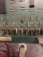
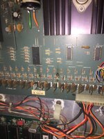
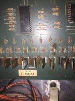
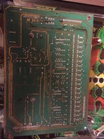
I’m back to using the old solenoid driver board ,the rotten dog one is useless
What all should I check before changing the coil again on left side flipper
Is this more likely to be the diodes ,transistors or is there something else I could be missing ? I’ve cleaned the eos and cabinet switch .
The left flipper is wired the exact same as right .
There’s no sign of life at all from cabinet switch
The other solenoids were disconnected because they were sticking on
So the machine is booting with no sound
The Outhole ,and two sling shots are disconnected
I put two new solenoids on the bottom flippers ,they worked until I put a solenoid on the Outhole (not a new one )
Something in coin door or cabinet switch didn’t like it
Now I don’t have the left flipper anymore
It’s not there in test mode either when holding switch in
I’m back to using the old solenoid driver board ,the rotten dog one is useless
What all should I check before changing the coil again on left side flipper
Is this more likely to be the diodes ,transistors or is there something else I could be missing ? I’ve cleaned the eos and cabinet switch .
The left flipper is wired the exact same as right .
There’s no sign of life at all from cabinet switch
The other solenoids were disconnected because they were sticking on
 Is it BPS022 the LEDs are 5V and 190V
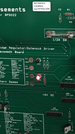
")