What's new
Pinball info

Register a free account today to become a member! Once signed in, you'll be able to participate on this site by adding your own topics and posts, as well as connect with other members through your own private inbox!

SOLVED - WPC-89 CPU Pin 5 on U11 goes to?

Andy B

Site Supporter
1 10 Years
Joined
Oct 6, 2014
Messages
1,424
Location
Hull. England.
I think I cut through a top of circuit board trace on my TZ CPU board when snipping a jumper (see non working knocker coil thread).

I got a switch row error message after I snipped the jumper.

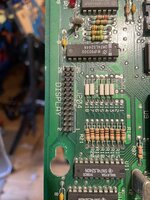
Physically examining the traces on the top of the board it looks like I have a break on the trace that comes off pin 5 of U11 and goes up the board to U7. The break is immediately beneath the top of the jumper I snipped.

I am absolute rubbish at reading schematics. Would someone mind reading the schematic please and seeing which pin on U7, pin 5 of U11 is supposed to be connected to so I can check for continuity please?

Thanks

Andy
 
Hi Andy,
U11 (74LS240), pin 5 is D2 and goes to many chips (which probably is your issue), on U7 (74LS244) it is pin 4. Schematics are here: https://www.ipdb.org/files/2684/Williams_WPC_Schematics_Revised_May_17_1993_.pdf

Perfect. Thanks. I hot wired those pins together.

I had those schematics thanks but could not make head nor tail of them because of the way U11 was shown as U11A and U11B. Now that you explained how the coding works ( U11 Pin 5 = D2 which connects to U7 D2 = pin 4) it (kind of) makes sense!

Using that same coding explanation and the photo uploaded by Calimori (thanks!) it also looked like I had a break in the track coming from U7 pin 15 which, if my understanding of the coding is correct = D5 and D5 on U11 = Pin 16. So I hot wired U7 pin 15 to U11 pin 16.

Didn't work.

Now getting switch row 2, 4 and 6 grounding error and clock broken message.
 
Sorted.

I had a further look at the board in the area around the jumpers that I'd snipped off and, with the aid of a magnifying app on my phone (Oh for the days when I had 20/20 vision!) could seem some damage to other tracks, not just the ones I'd fixed via wiring between pins.

So, with the help of my newly learned schematic reading skills I wired the following:

U11 pin 7 to U7 pin 15
U11 pin 3 to U7 pin 2
U11 pin 5 to U7 pin 4
U11 pin 7 to U7 pin 6
U11 pin 9 to U7 pin 8

Came up with switch errors but played a few games and once those switches had been hit I am getting no Test Report errors on boot up.

Thanks for the help
 
Back
Top Bottom