What's new
Pinball info

Register a free account today to become a member! Once signed in, you'll be able to participate on this site by adding your own topics and posts, as well as connect with other members through your own private inbox!

SOLVED (HOPEFULLY) - New flipper opto board - weird diagnostic menu issues - STTNG

Andy B

Site Supporter
1 10 Years
Joined
Oct 6, 2014
Messages
1,424
Location
Hull. England.
Was getting "Upper Left Flipper Not Working" message on STTNG. STTNG does not have upper left flipper but reading repair guide it says that if upper opto is not working on the 2 opto flipper board, machine will identify it as upper flipper error.

So I tested the upper opto and indeed it was not working. Bought a replacement opto board which sorted the "upper Left Flipper" error message out but that seems to be causing issues with the display and solenoids when I go in to the diagnostics menu. When the opto board is connected and I go in to the diagnostics menu, there are dots missing all over the display (see photo) and, when I try to test the solenoids and pull the interlock switch out, the left flipper (the one with the new opto board) slowly rises to the up position but none of the other solenoids work.

If I disconnect the opto board and enter diagnostics - no issues at all and all solenoids work with the interlock switch pulled out.

Anyone had anything like this before?

And I tell you what, It's dead spooky when the left flipper rises slowly - it's like it's possessed!

Obviously I can't be disconnecting the opto flipper board any time I want to go in to diagnostics.

Cheers

Andyimage0 (002).jpeg
 

Attachments

Last edited:
Hmm that's special!

So firstly, when you're in any part of the test menu, the flippers are enabled. So seeing one trying to energise doesn't suggest there is wiring fault or short between driver outputs.

You can clearly hear the gun kicker energise as part of your T.4-01 solenoid test.

Does the left flipper work OK during normal gameplay? If you're seeing the same behaviour, it might be the 'power' circuitry is at fault while the flipper 'hold' circuit is working ok.

The fact it energises by itself suggests your left opto board is triggering a ghost button press, either because the opto is faulty, or maybe soldered in backwards.

The fault itself may have been caused by fiddling to replace that opto board. The error message you saw about UL Flipper sw fault is a bit of a red herring. You're right that the game doesn't have an UL flipper, but that switch line on the fliptronics PCB is used for the spinner opto.

So it's probably the spinner opto at fault, or dirty, or the spinner is stiff and stuck horizontally, and that will have caused the error.

Replacing the flipper opto board won't have helped.

The other odd thing is you say the DMD becomes garbled ONLY when the opto board is connected? I feel like this should be unrelated and that there are several issues here. If not then I can only think that the bad opto has damaged the fliptronics board and in turn is causing it to hold a bit high/low on the data bus when it shouldn't be, via the U5 buffer chip (faulty, or a bad cable enabling it, or an ASIC reseat needed).

Otherwise it's just coincidence and maybe bad RAM or something.

Re-seat everything first and let us know about the flipper behavior and DMD during normal gameplay.

And does the spinner register?

Tim
 
Last edited:
Hmm that's special!

So firstly, when you're in any part of the test menu, the flippers are enabled. So seeing one trying to energise doesn't suggest there is wiring fault or short between driver outputs.

You can clearly hear the gun kicker energise as part of your T.4-01 solenoid test.

Does the left flipper work OK during normal gameplay? If you're seeing the same behaviour, it might be the 'power' circuitry is at fault while the flipper 'hold' circuit is working ok.

The fact it energises by itself suggests your left opto board is triggering a ghost button press, either because the opto is faulty, or maybe soldered in backwards.

The fault itself may have been caused by fiddling to replace that opto board. The error message you saw about UL Flipper sw fault is a bit of a red herring. You're right that the game doesn't have an UL flipper, but that switch line on the fliptronics PCB is used for the spinner opto. In fact you'll probably notice only one wire coming from the sw1 pin on the flipper opto board. On the fliptronics PCB, the other wire, usually for sw2, will come from the spinner opto receiver.

So it's probably the spinner opto at fault, or dirty, or the spinner is stiff and stuck horizontally, and that will have caused the error.

Replacing the flipper opto board won't have helped.

The other odd thing is you say the DMD becomes garbled ONLY when the opto board is connected? I feel like this should be unrelated and that there are several issues here. If not then I can only think that the bad opto has damaged the fliptronics board and in turn is causing it to hold a bit high/low on the data bus when it shouldn't be, via the U5 buffer chip (faulty, or a bad cable enabling it, or an ASIC reseat needed).

Otherwise it's just coincidence and maybe bad RAM or something.

Re-seat everything first and let us know about the flipper behavior and DMD during normal gameplay.

And does the spinner register?

Tim


Thanks for the detailed response Tim, I really appreciate it.

So I went and had a look at that spinner. It was testing good but it is a normal switch not an opto. I did notice the two wires from the switch were a little close together for my liking so I separated them and I also noticed there is no diode on the switch. I checked my pre-strip down photos and there wasn't one on it before but there should be a diode on every switch right?

I re-seated all connectors and data cables.

Went in to diagnostics. Everything working fine now and no garbled screen when I press both flipper buttons. Solenoids all working fine with interlock switch pulled out. EXCEPT left flipper switch wasn't registering again - only upper left - this with the old flipper opto board in. I confirmed lower left flipper not working in game also as I started Command Decision mode where you have to use flipper buttons to switch - right was working fine, left was doing nothing - I was having to press right flipper button to cycle around the options. I also confirmed lower left flipper opto on the old flipper opto board not working by sticking a piece of card in the sensor (which I could have sworn I did before I ordered the new one but you know how it is, you start doubting your own sanity when you really get in to troubleshooting a machine).

So...out with the old flipper opto board and in with the new. Enter diagnostics. Switch test. Lower left flipper button registering now as well as upper left. Woohoo, job's a good 'un - start a game. Left flipper comes up and holds as soon as start button is pressed and game starts. Grrr...

So...swapped the flipper opto boards over. Left for right. Diagnostics. Switch Test. All good. Lower left, upper left, lower right, upper right switches all registering. Start a game. Right flipper comes up and holds.

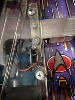
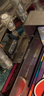
So it's the flipper opto board that's at fault right? But it's brand spanking new! Wait a minute, didn't I read somewhere that the actuators warp over time?

Physical inspection and the right actuator looks the same as the left. It's a different design, one has supporting gussets, the other does not but the dimensions look the same. So I swap the actuators over. Right for left. Start a game. Left flipper raises and holds. So the issue is moving with the actuator! Did a little bit of bending of the actuator causing the issues (it's on the left side now - are you following this Tommy Cooper like follow the issue routine?) and start a game and everything looks good and works fine.

Well, when I say everything I mean:

- I obviously haven't tightened the flipper bats properly as they're coming out of alignment, particularly the upper right one
- I need to check the switch for the top drop target as a ball goes in the ball lock hole and the target solenoid fires away until it gets bored and then stops
- The cannons are ever so slightly out of alignment
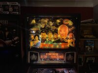
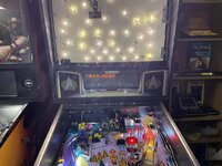
- The No Flix LEDs in the backbox look pants (first time I've dared tempting fate by putting the back-glass in and seen the full effect) - see photo below and confirm my opinion to be the right one - spots all over the place, except Patrick Stewart's face where I put some incandescents back in)
- One of the LEDs above the "Battle Simulation" insert is dodgy - I ordered them from Pinball Center and I have to say I'm not overly impressed, other than the fact that there is no ghosting which I have found I have got with other LED kits I've bought
- Need to buy two new flipper opto actuators

Andy
 

Attachments

  • IMG_5051.JPG
    IMG_5051.JPG
    87.1 KB · Views: 10
  • IMG_5049.JPG
    IMG_5049.JPG
    115.3 KB · Views: 10
Glad you got it sorted. The flipper actuators can be a tricky fault I’ve found.

I was blowing fuses and burning out coils ,working, not working, randomly holding etc on my sttng upper right flipper.
And after many questions on here and pm’s it was that little flap of plastic!

It’s always the ones you least suspect 😆
 
Just had a look at my strip down pics as I sold the pin, my spinner looks the same as yours with no diode.
 

Attachments

  • 824B549F-84E9-4CC2-B729-86E8D8E393F1.png
    824B549F-84E9-4CC2-B729-86E8D8E393F1.png
    190.2 KB · Views: 3
Opto bat!

Nice one Andy, glad you tracked it down!

Swapping things about and seeing if the fault follows is always a good way of testing.

The lack of diode on the spinner makes sense as it's not on the switch matrix. Fliptronics switches are all fed direct to CPU (ie not scanned rows/cols).

Cheers,

Tim
 
You're right that the game doesn't have an UL flipper, but that switch line on the fliptronics PCB is used for the spinner opto

The spinner is actually wired instead of the unused flipper End of Stroke, rather than the upper left button. Isn't the 'redundant' button opto used in the video mode?
 
I need to check the switch for the top drop target as a ball goes in the ball lock hole and the target solenoid fires away until it gets bored and then stops

Which of the drop target solenoids do you mean, the proper reset or the dropper? Star Trek Next Gen seems to have been plagued by problems with the smaller dropper solenoid. The mounting frame tended to break, allowing the droppers' metal plate (with finger attached) to move much further away from the solenoid than intended.

To check, while looking at the drop target, take off (or envisage taking off) the return spring for the dropper coils' plate/finger. If it can/could then simply be lifted/fall off, the frame has broken. The plate should be held in place by a metal bar, bent around to secure the plate and provide a stop for it at rest, with the finger close to the target. I saw more instances of this bar breaking off, with subsequent overheating of the dropper coil, on this game than others with the same arrangement (T2, Fish Tales, etc). Maybe there was a batch of bad ones, or someone clumsy on the production line.
 
Last edited:
The spinner is actually wired instead of the unused flipper End of Stroke, rather than the upper left button. Isn't the 'redundant' button opto used in the video mode?
Good call.. my bad.. have edited my reply v slightly so as not to confuse!
 
Good call.. my bad.. have edited my reply v slightly so as not to confuse!
No problems mate. I also found out the spinner switch does not need a diode as it is one of the direct switches which don't need a diode according to the repair guide.

I played the thing to death until around 1am this morning and fixed the top drop target switch.

Went to switch it on this morning to start working on the other minor issues and now the display is not working at all!

I have good voltages from J604 on the driver board - though when I measured pin 2 the first time it read 93.90 which was 22 less than the 115.01 at pin 1 when repair guide says gap needs to be 12v. Re-seated connectors and pin 2 is now at 103.9, so 12v difference from pin .

Even though I was getting the correct voltages at J604, just for good measure (you see what I did there :-)) I measured the voltages coming from J604 on DMD Controller board. All good. Measured voltages coming from transformer to DMD controller board. They're around half what they should be - coming in (Pin1=42.2V, Pin 2=39.0V, Pin 3=58.6v, Pin 5=40.6V) - but I'm guessing that could be because they're not under load when I'm measuring from the connector with it disconnected?

I removed the DMD Controller board and reflowed all the soled on the connectors. Tested fuses. Good. Disconnected and reconnected all the connectors from transformer under playfield.

Will start a new thread for this one...
 
Back
Top Bottom