What's new
Pinball info

Register a free account today to become a member! Once signed in, you'll be able to participate on this site by adding your own topics and posts, as well as connect with other members through your own private inbox!

Sega lamp matrix question

cooldan

i like pizza
10 Years
Joined
Jul 21, 2011
Messages
7,102
Location
Ealing, London
Hi guys. So in a Space Jam I have lots of lamps out and all in the same column. The only ones that *aren't* out are on mini boards with a connector rather than individual wiring, and these have a strange LED bulb in place - the game is otherwise safely LED-free and these are fixed rather than blinking in 'all lamp' test..... so it looks to me that this isn't a new issue.

So the game tells me they are all in column 8, and that they are linked by the yellow/grey wire originating from pin1 of J13 and controlled by a transistor at U10. I look under the playfield and indeed can see this wire going to all the locations in this column. No obvious breaks.

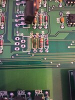
Next I look at the board. A quick visual around U10 makes me think the resistor to the right of it has gone black and is my first suspect. Look at my pic to see what I mean - it's the bunch down in the bottom right
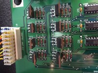
images.tapatalk_cdn.com_15_12_15_f287acd4af8fc6ae9bafb874c7cdedcc.jpg

Now I'm not the best at reading manuals but I think this thing at U10 is a VN02N. Google tells me that this is a TO-220 style but I can't work out from the pinwiki site how to properly test this thing. So I thought I'd compare it to its neighbours but am getting nowhere.

My questions-
-How to test this thing at U10?

-Is there any point with that black thing next to it, should I just try to source that first or would it have taken other bits down with it when it died?

-what's the trick to confirm that the problem indeed lies on the board and not on the playfield?

-anything else I'm missing regarding the Sega lamp matrix?

Dan
 
I've never had a Sega machine so not familar with their boardsets. I tried to have a look at the schematic for the board on IPDB but the scan is really poor quality and not legible. If you can upload a decent scan of the lamp matrix part of the schematic I'll probably be able to help you further as I'm working half blind here, however to try and answer your questions in the meantime:

To prove that the problem lies on the board, unplug the lamp matrix connectors to isolate the playfield. It may be worth measuring the resistance between ground and each of the pins on the connectors to check you don't have any shorts on the playfield. Theres definitely a problem with your board now however the root cause of the problem may be on the playfield.

The "thing" at U10 is a solid state relay, essentially just an electronic switch allowing the low current logic circuitry to drive the lamp matrix. According to the datasheet this component should have built in short circuit protection so theoretically a short on the playfield shouldn't cause it to fail.

The "black thing" at R261 used to be a 1/4 watt resistor however its clearly been forced to dissipate significantly more power than it was designed for and has blown. Just looking at it tells me theres no way its in spec anymore and it WILL require replacing! Resistors don't just fail like that, a short somewhere else has caused it to blow and in this case most likely an internal short in the chip at U10. Its only a 1/4 watt resistor so will likely be somewhere be connected somewhere on the low current logic side of the chip at U10. (Remember I haven't seen a legible schematic here!) Brief research suggests these chips are normally fairly reliable but they do fail.

The only way you can really test U10 is with the game running. The datasheet for the component explains what it does and what pins do what:
http://www.st.com/web/en/resource/technical/document/datasheet/CD00000025.pdf

With the board in its current condition and assuming you have a logic probe or a scope, the next thing I would do is test the input to the chip on pin 2 is moving as it should and isn't locked on. ( Its the second pin down from the top in your photo.) You can look at the inputs in to the other chips to compare, its probably best to put the game into lamp test where you should see a steady repeating signal. I doubt you should see a problem here however if you do then there is probably a problem with the logic circuitry further upstream. (Again I haven't seen the schematic so this may not be the case as its possible that the line is being held high or low by a fault elsewhere.) If the chip is working properly then the output at pin 5 should look exactly the same as the input at pin 2. If the power supply at pin 3, ground at pin 1 and input at pin 2 are all good but the output at pin 5 is not then the chip is knackered. (In my opinion this is most likely the problem.)

If you are sure you have no shorts on the playfield then change the chip at U10 and the resistor at R261 and you should be good to go. If you want to test this theory before ordering parts then desolder the parts from another column and move them in to the broken one, if the column starts working as expected then you've found your problem. This should be pretty straightforward if you have a desoldering station. Keep an eye on the components when you switch back on and be ready to turn off quickly.

If your're struggling to make sense of any of this and just want a quick fix then I'd just change U10 and R261 anyway as I'm reasonably confident this is where your problem lies. Providing the board has the correct rated fuses fitted, realistically the worst thing that can happen is you blow up another resistor and VN02N if the problem lies elsewhere. :thumbs:

EDIT: I've just managed to find a legible schematic for the board and can see that R261 is a resistor between pin 1 on the VN02N and ground. Its failure says to me there must be an internal short in the VN02N at U10. To test this theory measure the resistance between pin 1 and pin 3, its probably dead short. Compare this to a known good VN02N on another column, you should see a decent resistance.

So that quickly become a lot more complicated then it needed to be but I've written it now so I'll leave it there!

The short answer: Change the VN02N at U10 and the 47 Ohm 1/4 watt resistor at R261. (The spec of this resistor seems to be written wrong on almost every schematic and list I have seen, but it should be 47 Ohm not 47k!)
 
Last edited:
Have you checked the fuse and connector for said column before attempting any board work
The whole lamp matrix is protected by a single 8 amp slow blow fuse (F22.) If this had blown none of the controlled lamps would work!
Compare the resistance across the black resistor to the ones above to see if its still in spec.
You really don't need a meter to tell you a resistor that looks like that isn't in spec, its clearly open circuit!
 
I'm sure the guys above are right and changing U10 and the Resistor are the way to go. I'd be tempted to use the Diode setting on your DMM first and measure between the middle tab and outer terminals (machine off) of U10. If you get different readings to the other ones around it you know for sure its duff and defo time to heat the soldering iron up.

Btw, if it does test the same as those around it may still be bad!
 
Last edited:
tried to have a look at the schematic for the board on IPDB but the scan is really poor quality and not legible. If you can upload a decent scan of the lamp matrix part of the schematic I'll probably be able to help you further
yeah it's crap innit, but that's all i have too. would love if someone has it, if they could upload it.

To prove that the problem lies on the board, unplug the lamp matrix connectors to isolate the playfield. It may be worth measuring the resistance between ground and each of the pins on the connectors to check you don't have any shorts on the playfield. Theres definitely a problem with your board now however the root cause of the problem may be on the playfield.
this is just what i wanted, thanks mate - applies to all electronic pins i think for both switch matrix and lamp matrix - so how do you do it? i know you have to remove a/some connector(s) and try shorting stuff to other stuff with a wire +/- a diode on it. i never understood exactly this bit in detail and would love to know.

The "thing" at U10 is a solid state relay, essentially just an electronic switch allowing the low current logic circuitry to drive the lamp matrix. According to the datasheet this component should have built in short circuit protection so theoretically a short on the playfield shouldn't cause it to fail.
so it's a transistor of sorts, like mosfets are? i'm happy in my ignorance on this one.

The "black thing" at R261 used to be a 1/4 watt resistor however its clearly been forced to dissipate significantly more power than it was designed for and has blown. Just looking at it tells me theres no way its in spec anymore and it WILL require replacing! Resistors don't just fail like that, a short somewhere else has caused it to blow and in this case most likely an internal short in the chip at U10. Its only a 1/4 watt resistor so will likely be somewhere be connected somewhere on the low current logic side of the chip at U10. (Remember I haven't seen a legible schematic here!) Brief research suggests these chips are normally fairly reliable but they do fail.
ok, so presumably this burnt sausage would need replacing along with U10 ... what about the other sausage to its right?

The only way you can really test U10 is with the game running. The datasheet for the component explains what it does and what pins do what: http://www.st.com/web/en/resource/technical/document/datasheet/CD00000025.pdf
sweet, will try this later

With the board in its current condition and assuming you have a logic probe or a scope, the next thing I would do is test the input to the chip on pin 2 is moving as it should and isn't locked on. ( Its the second pin down from the top in your photo.) You can look at the inputs in to the other chips to compare, its probably best to put the game into lamp test where you should see a steady repeating signal. I doubt you should see a problem here however if you do then there is probably a problem with the logic circuitry further upstream. (Again I haven't seen the schematic so this may not be the case as its possible that the line is being held high or low by a fault elsewhere.) If the chip is working properly then the output at pin 5 should look exactly the same as the input at pin 2. If the power supply at pin 3, ground at pin 1 and input at pin 2 are all good but the output at pin 5 is not then the chip is knackered. (In my opinion this is most likely the problem.)
?? which chip, which pin? you lost me - i'm assuming that U10 is not a chip, are you talking about those three chips on the right, U209, U18, U6? anyway i haven't got a logic probe or scope and am not at the sill or underatnding level yet to use these even if i borrowed them.

If you are sure you have no shorts on the playfield.....
how do i establish this?

....then change the chip at U10 and the resistor at R261 and you should be good to go. If you want to test this theory before ordering parts then desolder the parts from another column and move them in to the broken one, if the column starts working as expected then you've found your problem. This should be pretty straightforward if you have a desoldering station. Keep an eye on the components when you switch back on and be ready to turn off quickly. If your're struggling to make sense of any of this and just want a quick fix then I'd just change U10 and R261 anyway as I'm reasonably confident this is where your problem lies. Providing the board has the correct rated fuses fitted, realistically the worst thing that can happen is you blow up another resistor and VN02N if the problem lies elsewhere. :thumbs:
i prefer to minimise my soldering and especially desoldering, as that is where problems occur at my level of ability and tools (just a soldapullit), so i will skip this step

EDIT: I've just managed to find a legible schematic for the board and can see that R261 is a resistor between pin 1 on the VN02N and ground. Its failure says to me there must be an internal short in the VN02N at U10. To test this theory measure the resistance between pin 1 and pin 3, its probably dead short. Compare this to a known good VN02N on another column, you should see a decent resistance. So that quickly become a lot more complicated then it needed to be but I've written it now so I'll leave it there! The short answer: Change the VN02N at U10 and the 47 Ohm 1/4 watt resistor at R261. (The spec of this resistor seems to be written wrong on almost every schematic and list I have seen, but it should be 47 Ohm not 47k!)
pin 1 and pin 3 on what?

Have you checked the fuse and connector for said column before attempting any board work
what Aaron said

Compare the resistance across the black resistor to the ones above to see if its still in spec.
what Aaron said

by the look of that pic the resistor is fried i would suspect the transistor is also damaged
that's the plan

cheers fellas for the detailed and helpful answers. to my great surprise, in my little kit with diodes and transistors and stuff, i found one 5-legged one labelled 'mosfet VN02N' which i presumably got 'just in case', but the only little bag of resistors i have are a different stripe pattern. could you maybe point me to a page with the commonly used pinball resistors on it so i can grab a selection for next time?
 
If you have a spare VN02N thats really good as they're the harder bits to get hold of. PM me your address and I'll pop a couple of resistors in the post to you if you like. They're really cheap, you should just be able to buy a packet with loads of different values to cover most applications.

If you don't have a proper desoldering station just cut the legs on the 2 components as they're definitely knackered, then pull the legs out one by one and clean up the solder afterwards. Its a lot safer if you're not a confident solderer, the last thing you want to do is rip out the plated through holes.
 
this is just what i wanted, thanks mate - applies to all electronic pins i think for both switch matrix and lamp matrix - so how do you do it? i know you have to remove a/some connector(s) and try shorting stuff to other stuff with a wire +/- a diode on it. i never understood exactly this bit in detail and would love to know.

That procedure is for testing the board side and is described here for row and columns http://techniek.flipperwinkel.nl/desega/index3.htm#lamp
 
I'm sure the guys above are right and changing U10 and the Resistor are the way to go. I'd be tempted to use the Diode setting on your DMM first and measure between the middle tab and outer terminals (machine off) of U10. If you get different readings to the other ones around it you know for sure its duff and defo time to heat the soldering iron up.

Btw, if it does test the same as those around it may still be bad!

U10 isn't a transistor, its a solid state relay. Essentially it does the same job a transistor would but adds other stuff like short circuit and thermal protection. This is why it has 5 legs instead of 3. This chip is grounded through the resistor that has blown at R261. As its the only thing that can ground through that resistor then its safe to say its the culprit.

Pin 1- Ground
Pin 2 - Input
Pin 3 - VCC (Power supply in other words)
Pin 4 - Status
Pin 5 - Output

That procedure is for testing the board side and is described here for row and columns http://techniek.flipperwinkel.nl/desega/index3.htm#lamp

Space Jam runs on the later Whitestar boardset and the lamp matrix is a different design so unfortunately these pages are of limited use. :(
 
@aaronhicksuk you are defo an authority on this, I recall you helping me identify the obscure problem on my Rottendog MPU.

Back to this, if I read the above correctly you are advising Dan to test the play-field wiring side for shorts also in case there is an underlying fault causing the board problem. Not nice fitting new components to find they pop straightaway caused by something else - have been there!
 
so how to rule out that i also have a playfield issue that may even have caused the board to fry? i see the wire coming and going, how do i know that all is well?
 
@aaronhicksuk you are defo an authority on this, I recall you helping me identify the obscure problem on my Rottendog MPU.

Back to this, if I read the above correctly you are advising Dan to test the play-field wiring side for shorts also in case there is an underlying fault causing the board problem. Not nice fitting new components to find they pop straightaway caused by something else - have been there!

Thanks for the kind words @astyy. Electronics isn't my day job so I wouldn't say I'm an expert at this stuff like @lukewells and @myPinballs etc. I've always had an interest in this stuff though and have a reasonable grasp of the basic principles which allows me to research and understand specifics. It may not seem so but in the grand scheme of things the electronics in a pinball machine are actually pretty simple stuff. One of the many things I love about pinballs is that they can be repaired with relative ease, something that has sadly been lost with most things in the modern world. Even pins seem to be heading this way too now though. :(

Anyway yea you read correctly, I was advising Dan to test the playfield wirign for shorts in case there is an underlying fault to cause the board problem. Its still a good idea to be on the safe side but I wrote that before looking at a decent schematic. In this case I'm actually fairly confident that the playfield wiring will be fine as: 1) the VN02N is supposed to have short circuit protection to theoretically even a playfield short shouldn't kill it. 2) The resistor that has blown only provides a path to ground for the VN02N and nothing else, so the short that killed it would appear to be within the chip.
 
so how to rule out that i also have a playfield issue that may even have caused the board to fry? i see the wire coming and going, how do i know that all is well?
Unplug the connector at J13 and measure the resistance between each of the pins and ground. You should see a decent resistance well above zero ohms or an open circuit. The resistances of each should be similar to each other.
 
partsch.png

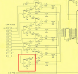
The 2 components in question are highlighted in the red square above. If R261 is open circuit then the lamps won't work as it provides the path to ground for the VN02N. Resistors don't just just blow up without a cause though, in this case there must be a short within the VN02N. :)
 
Unplug the connector at J13 and measure the resistance between each of the pins and ground. You should see a decent resistance well above zero ohms or an open circuit. The resistances of each should be similar to each other.

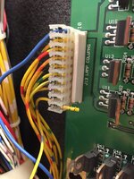
lamp matrix.JPG
pin 1 (row 8, my trouble row) 0.4M ohm
pin 2 (missing, key)
pin 3-9 (rows 1-7, all working) 1.6M ohm
pin 10 (no idea where this goes) 0.4M ohm

does this confirm that the board has the fault?
and is there a way to check that the playfield wiring is ok?
 
Sorry mate, I meant to check the resistances of the pins of the disconnected connector to ground to check for playfield shorts.

What you have done is cool though and confirms what we already know.

You can ignore pin 10, its supposed to be an 18v supply.
 
Connector terminology can be confusing as both sides are Terminal Pins - Male Header Pins on the PCB and Female Terminal Pins inside the cable connector.

With inline wire-to-wire connectors it gets worse as the Male plug housing typically contains the Female terminal pins whilst the Female socket housing contains the Male terminal pins.
 
Thanks Aaron for sending me the resistor in the post. I replaced these two parts and then with a bit of a wiggle (a wire also came loose from an IDC but I think that was during the board removal, pretty sure it wasn't the cause as the multimeter showed the board components were toast) it's now all fixed.


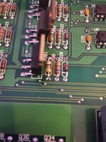
images.tapatalk_cdn.com_15_12_17_0a286ec5f752917dab6f9b3d9ae506b2.jpgimages.tapatalk_cdn.com_15_12_17_01f43e9565de86018fae347b160a6489.jpg images.tapatalk_cdn.com_15_12_17_896c7c6853d8dc55e7741d961eed30ed.jpg
 
This must be contagious, just noticed the Lazer Kick wasn't firing on HOOK, voltages good at the coil, fired when shorted to ground etc. Then found the smoking gun - that's a proper blown resistor.

upload_2015-12-17_15-16-48.png
 
presumably also caused by the failing transistor?

when it comes to soldering, i'm ok when i can hold the iron in one hand and either the sucker or the solder in the other, while gravity keeps the bits in place, so boards i can usually have a decent effort at. but when it comes to a simple wire off a coil/switch, i just can't do it without an extra hand to keep the ****ing thing where i need it to be while i'm soldering. i end up with balls of solder falling god knows where and causing mayhem, huge regmaglypts of cold solder, and nothing holding fast. i need an extra arm, dunno how you guys do it
 
presumably also caused by the failing transistor?

I'm not sure Q4 is diode testing same as the others and when it shorted before it locked the coil on and then blew its fuse. I have spare TIP36C and the 1N4004 but not the 220 Ohm Resistor so have just ordered some.
 
Back
Top Bottom