What's new
Pinball info

Register a free account today to become a member! Once signed in, you'll be able to participate on this site by adding your own topics and posts, as well as connect with other members through your own private inbox!

Sega baywatch 5v issue

Asiapinball

Site Supporter
Joined
Aug 14, 2020
Messages
1,070
Location
near Hexham
Alias
Paul
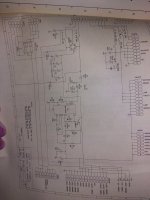
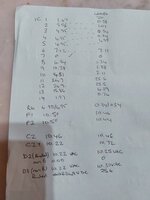
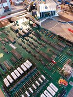
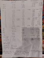
I have an issue with my baywatch 5v. 5v at psu seems to be fine if run without load but if cpu is connected (and nothing else) to 5v drops down to 0.38v and hence cpu will not boot. Plus and minus 12v stay OK both at about plus or minus 13.9v. Cpu will boot using old PC power supply and all diagnostic leds do as they should. I am suspecting 723 ic on psu and or c2 c3 and c7 and I could go ahead and just change them and see. However I would prefer to understand what is going on for future diagnostics. Game is one that i acquired several years ago non working. Board is original as are all the caps and 723 ic. I have several spare psu boards and they all do the same, which is why I am questioning whether it is the psu or the cpu that is at fault. Image shows voltages on psu both with and without cpu load . Psu has good connectors and fuse clips.

Questions are

1. Is it an issue with cpu or psu
2. Is 25v dc correct at pins 11 and 12 on 723 ic as I have other psu where this is about 14v
3. If psu, where is the fault most likely to be. Is it the 723 or the caps at c2 c3 and c7 or elsewhere.
4. As 12v all OK does this mean that c11 c12 c13 c14 and Bridge rectifier probably all OK.

Thanks,

Paul
 

Attachments

  • 20220219_144908.jpg
    20220219_144908.jpg
    59.5 KB · Views: 10
Hi Paul. eggs were fantastic by the way! 👍😃

If you have swapped in a spare psu, and still doing it surely that points to something else - ie the mpu? any other boards use the 5v? it might be one of those?
 
Hi Paul. eggs were fantastic by the way! 👍😃

If you have swapped in a spare psu, and still doing it surely that points to something else - ie the mpu? any other boards use the 5v? it might be one of those?
I'll try to bring you some more to the next meet. Hens are overrunning us at the moment. Can't keep up and getting sick of eggs.

That was why I was doubting whether psu or cpu. I have several psu that all do the same but the cpu will boot on the PC power supply and I know that caps on the psu are generally troublesome particularly as they are all 25 years old now so maybe I have a working cpu but ust have a load of psu that have 25 year old and leaked electrolytic caps. I was hoping for an electronics whizz on the group to look at the voltages and tell me exactly what is wrong with it. For me this is as much about the learning experience. There are various similar threads on pinside but most don't conclude how it was fixed so not that helpful.
 
Just had a quick look at the schematic - I'd suspect that perhaps all the PSU's you have tried are duff. - The 5V is generated by the voltage regulator chip and the power is drawn through TR5 2n6057 - the big T03 transistor on the heatsink - I would say it is that that has failed, so under no load it shows 5v - but as soon as you put it under any sort of load it drops to near zero.
 
Definitely psu board. I just pulled another psu out of the box of 7 that I have and cpu is now booting so at least I have proved cpu OK
 

Attachments

  • 20220219_160956.jpg
    20220219_160956.jpg
    189.9 KB · Views: 10
Do your hens lay psu boards too? 😂😂
Wish they did. Cpu boards would be better.

The psu boards were from baywatch and batman forever that I parted out many years ago when I lived in Malaysia. Termites had eaten the cabinets but found the rest of the machines not to their taste.
 
Thanks, Chris. Seems that is the goto component.
Paul, change it as a matter of course, but I still bet my money on the power transistor? why? Well because you are getting +5v (suggests power regulator working ok, so C2 still functioning, but could be faulty). The 5v is collapsing under load, that to me suggests the power transistor has failed. The load power doesn't come via C2.
 
Paul, change it as a matter of course, but I still bet my money on the power transistor? why? Well because you are getting +5v (suggests power regulator working ok, so C2 still functioning, but could be faulty). The 5v is collapsing under load, that to me suggests the power transistor has failed. The load power doesn't come via C2.
I just changed the c2 and it has made no difference to any of the voltages. But old one was leaking so needed doing anyway. I don't have any new 2n6057 so will need to get some or might just pull one from a very ugly board. I just buzzed out the 6057 and there is continuity so it is shorted. The one on the ugly board buzzes out OK. Interestingly the boards that came from Malaysia all have 6056 in them and the ugly board that came with the machine that I bought here has a 6057.

Thanks for all the help. I definitely owe you some eggs.
 
Just swapped the transistor over from the ugly board i had and the psu now works. So it was the power transistor. And the voltage edged up slightly so hopefully it is sufficient for running the big dmd too. I will also swap out the other caps as the board is out of the machine.

Thanks again for your help, Alan. Time for a well earned beer now.

Paul
 
Maybe all the boards I had from Malaysia had faulty power transistors. It may explain why 8 machines were all lined up in a row non working.
 
Could be that the Malaysian boards all had 2n6056 which are lower spec than the 2n6057. From the serial numbers I expect all the machines were shipped at the same time and all the transistors are same manufacturer same stamping and hence could be from the same batch. so maybe sega just couldn't get the 2057s at the time so substituted a lower specified part. Looks like I will be ordering a few 2n6057s for repairs
 
Brill - they’re the weak point , not because they’re wrong spec, but any sort of short is gonna strain them. plus it’s only a transistor. and they take a ton of power considering the size of the silicon junction inside then
 
I installed the psu back in the machine and all is now working. Big dmd and sound board working. Was fixed by changing c2 and tr5 on power board. 5v is at 4.96v and possibly marginal as I got the "Baywatch will be right back" call out which indicates a sound board reset probably as a result of low 5v. At the weekend I will pull the psu board and replace c3 and c7. I also read in previous post that replacement of 723 regulator chip resulted in around 0.2v increase in 5v so will also do that.

I have 8 of these boards in total 2 of which have been previously hacked beyond decent repair and I have diagnosed the other 6 over the weekend and fixed 2 of them. But I need parts to fix the others but wanted to document what I have learned from the exercise for pinheads in a future timezone.

Note that I had good plus and minus 12v on all the boards so am only commenting on 5v issues.

On Diagnostics what I have learned is

1. If 5v OK with no load but drops with load then test each end of R6 on psu and if there is a large drop in voltage then issue is with cpu or another board and not the psu. If little or small drop say about 0.1v then issue is with psu.

2. If 5v is low even when there is no load then likely culprit is c2 and you should change that first. In my case one board increase from nil load 5v from 1.63v to 4.90v and also fixed the 25v at pins 11 and 12 of ic1 which measured just 7.2v prior to changing c2.

If issue is with psu then

3. You can check condition of c2 by measuring ac voltage on each leg of c2. This can be done in situ by measuring ac at f1 and ac at the banded end of d2 (Black lead to ground). Should be something a little over 10v ac at both with a drop of about 0.1 to 0.15v. If drop is any more then c2 needs replaced. Replacing c2 increase 5v In my case by about 0.05v.
3. If 5v OK with no load but drops massively under load then suspect tr5. This can also be tested using usual DMM continuity test process for transistor testing (with power off). 2 of my boards had shorted tr5.
4. Correct dc voltages on ic1 chip pin by pin are 2,3,4 and 5 5.0v, 6 7.1v, 7 0.0v, 10 6.4v, 11 and 12 25.0v, 13 7.7v. These were taken from working boards albeit with voltage still a little low.

Although i now have a working board (and a spare) to get the 5v higher I intend to replace c3 and c7 and ic1 regulator chip at the weekend and will post the results of that here.

Hopefully this will be of help for others diagnosing these boards or other Data East boards which have same 5v layout.

Thanks to AlanJ and ChrisB for helpful hints along the way.

Paul
 
Last edited:
My Baywatch broke down last night doing all sorts of srtange things and no display. I have basically no electronics knowledge but am willing to give it ago if someone can steer me in the right direction . I do have a fluke multimeter and what I think reasonable soldering skills, I am only getting 2,9v on the test point. All fuses and clips are good. Would it seem like the best point to start by changing Caps C2 (100uf 25v), C3 (47uf 63V), and C7 (330uf 25V) and C4 with the 15,000uf/25V as on Pinwiki.
Don't forget to treat me like I know nothing.
 
Check the ac voltages at the fuses first.

If those OK, C2 is most likely the culprit of low 5v and if it has leaked it often destroys the continuity of traces in the area. I would just change that one first.

The 4 larger caps in a row on the board don't usually need changing.
 
Here is pre and post test voltages for a board I partially fixed by changing c2 only. This will give you what you should expect across the board voltage wise.
 

Attachments

  • 20240409_100056.jpg
    20240409_100056.jpg
    94.1 KB · Views: 11
Check the ac voltages at the fuses first.

If those OK, C2 is most likely the culprit of low 5v and if it has leaked it often destroys the continuity of traces in the area. I would just change that one first.

The 4 larger caps in a row on the board don't usually need changing.
You will even have to tell me exactly how to test those. ;) The board is out of the machine at the moment. Should I just get the Cap first and change that first whilst its out
 
If the board is out of the machine it is worthwhile changing C2 first and seeing where that gets you as that is most likely the culprit. Just make sure the traces are intact around C2 on the board when you do it and clean up anything that may have leaked from the old C2 capacitor.
 
Circuit is relatively straightforward. I would start checking the circuit starting at cn1 pins 10 and 11 and work through from there' left to right.

I.e start by checking the ac voltages at f1 and f2.

And also what is your 12v dc reading at tp3?
 

Attachments

  • 171286869932232252921427672798.jpg
    171286869932232252921427672798.jpg
    96.7 KB · Views: 7
  • 17128687573404410929805842968338.jpg
    17128687573404410929805842968338.jpg
    73.8 KB · Views: 8
Sorry for the delay but unfortunately life gets in the way of a lot of things. Any help is much appreciated , I have still only changed C2
TP1 2.6 vdc
TP3 7.88vdc
F1 9.7vac
F2 10.98vac
CN1
Pin 10 9.86vac
Pin 11 11vac
 
Your 12v is also low at TP3, so it is an issue with both the 12v and the 5v.

You have OK ac at the fuses, so it is likely the big square bridge rectifier on the board.

You can take the board out of the machine and test the bridge rectifier like this

The only other thing it may be is the fuse clips on the bridge rectifier of fuses 1 and 2 - so check you have good continuity between the each of the fuses and the corresponding connection point to the bridge rectifier.

But before pulling the board, take off all the connectors other than CN1 and test the 12v and 5v at TP3 and TP1. If they remain low then it is definitely a problem with the Bridge rectifier or the fuse clips on the board.

Removing the bridge rectifier off these boards is a pain unless you have a desolder station. The bridge has big square lugs so lots of contact with the board so lots of desoldering.

Paul
 
Back
Top Bottom