What's new
Pinball info

Register a free account today to become a member! Once signed in, you'll be able to participate on this site by adding your own topics and posts, as well as connect with other members through your own private inbox!

In Progress Seeburg ESB100 Jukebox

Quick initial look:

This one comes with the optional remote (wired) volume control and record rejection button.

The volume up and down switches control a motor in the main box, which turns the volume control potentiometer up or down!

IMG_7409.webp

There is an extra (speaker?) wire coming out of the back.
IMG_7410.webp

The rear cover plate is bent and hanging off.
It covers the selection Tormat, which is a complex and delicate component, so I’m hoping it hasn’t been messed with!
IMG_7412.webp

The main front door lifts up and should lock into place but the locking components are broken and part missing on one side and totally missing the other side. Why would anyone remove those……grrrr
IMG_7413.webp
IMG_7414.webp
I’ll look for replacements but may have to make some or get some made.

Internal components all seem to be there
IMG_7415.webp

IMG_7417.webp

Crack in the insert artwork top left. Not major
IMG_7418.webp

The chrome (over plastic) is bubbling and flaking.
IMG_7419.webp

The main door won’t close and lock properly. It looks like it’s bent and falling apart - a large gap at the top, both sides
IMG_7420.webp
IMG_7421.webp

Plenty of cobwebs and dead 🕷️.

My plan is to get it going first, then look at the cosmetics, once I know it’s worth the effort.

I’ll remove and inspect all the major electronic components and interconnects, (most plug in and are easy to remove). If all looks good I’ll power it up and see what happens.

Tomorrow I’m hosting a pinball comp, but may get a chance to do a bit more work on it.
 

Attachments

  • IMG_7407.webp
    IMG_7407.webp
    102.4 KB · Views: 3
I can’t safely work on this machine until the door is fixed, so first job is to mend the broken corner bracket

IMG_7434.webp

I prepped the metal to bare steel and held tight between two pieces of wood

IMG_7435.webp

Added an extra metal piece and welded it
IMG_7436.webp

a bit of adjusting and removing extra metal to make it fit, it’s not pretty but the door is now firmly held together and closes properly
IMG_7438.webp
IMG_7439.webp

I now need to make a pair of retaining hinges to hold the door open when it’s lifted up.

Something like this:
IMG_7433.webp

Nothing off the shelf is the right size, so I’ll make from bare fixing plates. Ordered from eBay. Should arrive later this week.
 
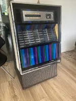
Now the door frame is mended, I can prop it up with a piece of wood to work on the components inside.
IMG_7443.webp

I powered on and the record player mechanism sprung into life and selected a record and started playing it. I rejected it using the wired remote and the next record was selected for playing. I rejected again and it continued to select the next record. It was playing "B" sides, then when it got to & played the first record in the rack it switched to going through all the "A" sides....., then back round to the "B" sides. There is obviously a fault with the read-out from the Tormat - I'll look into that later.

I also noticed I could select as many records as I wanted, - It appears maybe to have ben modded to free-play (but not sure). The selection relay is pulled in all the time, which isn't a great idea as the coil starts to get warm/hot after 5 minutes or so. (Back in the day, a customer would enter a coin and maybe take a few minutes making their selections, then the coil would de-energize, so it was designed to hold in for at least a few minutes, but not for hours on end). This is another thing I need to take a closer look at.

The good news was I got some sound out of the speakers. On closer inspection I noticed only the Right hand channel speakers were producing any sound. There is a top tweeter horn and a bass speaker in the bottom of the cabinet. I checked the wiring of the speakers to the amplifier and all is wired correctly. I swapped the left and right speaker wires and the sound switched to the other speakers (however I noticed the left tweeter isn't working, but the bass speaker was). SO: We have an issue with the left channel amplifier and also a duff tweeter on the Left channel. I tested the tweeter resistance and it's open circuit - so will have to source a new tweeter.

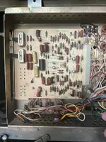
On to the amplifier. It's a SHA2 Seeburg Solid State Amplifier. The amp is housed in a metal case that opens to reveal 2 circuit boards and some discreet components. On the reas are 3 transformers, a relay, 4 power transistors on a huge heatsink and all the input and output connectors.

I checked the signal from the stereo cartridge and it is outputting both Left and Right Signals OK.

The 2 boards are the pre-amp and the main power amp. The pre-amp is situated behind the power amp.
IMG_7445.webp

I made a harness to hold the poweramp out of the way, so I could get to the pre-amp and do some tests with the power on:
IMG_7447.webp

The pre-amp seems ok, it's generating both L & R output signals ok. and those signals are reaching the power amp board.
I decided to re-cap the pre-amp anyway.
IMG_7440.webp

I snipped legs of some caps and tested them - they were way out of spec - they're 50 year old, so time to replace.
IMG_7441.webp
IMG_7442.webp

Another test and still no Left channel.

The Power amp has an edge connector (so does the pre-amp), but 4 connections are belt & braces soldered to the board as well:
IMG_7446.webp

It seems that the early amps didn't have this mod and problems were reported with the power transistors blowing up. Those 4 connections are for the bias circuit and go out to a potentiometer for each channel. If the edge connector loses connectivity momentarily, there is danger of overload and blowing the output transistors. Hence the hard wired fix.

I tested the on board output stage transistors NPN and PNP for both channels. They all appear ok.
IMG_7448.webp

I unscrewed the heatsink to get to the final stage power transistors, and again all 4 tested out ok with a meter (not a full test as there are driven at +32 and -32v, so they could still be the problem).
IMG_7450.webp

Next job is to recap the main amp board and see if that solves the issue.
If not I'll have to chase the signal through the circuit board.
 

Attachments

  • IMG_7444.webp
    IMG_7444.webp
    118.9 KB · Views: 1
Recapped the main amp board and it’s made no difference to the missing Left channel. Ive disconnected the right side temporarily so i can hear the left side. The bass speaker is humming which is a good sign, started to trace the signal through the board using:
IMG_7462.webp

For a bit of light relief I’ve done a couple of minor jobs :
1. Cleaned the horrid label marks off the sides;
Before:
IMG_7464.webp

After:
IMG_7460.webp
IMG_7461.webp

2. Replaced the coin box door lock as it had no key:
IMG_7463.webp

Pic of the rear amp box that I forgot to post earlier

IMG_7459.webp
 
This morning has been about finding the issue in the Main Amp left channel. Whilst measuring various test points, the left channel suddenly started working. Possible explanations are "loose wire" or "loose edge connector", or "loose component" or "failed/failing component". I've already established that the audio signal is arriving into the board ok, so am ruling the first 2 out.

I inspected the rear of the board and there are no cracks or loose connections. So I'm left with the "failed/failing" component.

Here is the Left channel circuit diagram:


1753790600215.webp

The signal comes in bottom left into a pair of transistors - these are set up as a differential amplifier, comparing the input and the output signals. - The output signal is from Q5122 straight into Q5124.
As far as I can test, Q5122 and Q5123 are working correctly and the input to Q5124 also appears correct. Q5124 is effectively a voltage gain that feeds into the driver transistors Q5125 and Q5126. The output of
Q5124 seems incorrect and I think that transistor is the issue.

I powered off and left the system for an hour. When I returned and re-powered up, the Left hand channel was missing again. I probed Q5124 with my meter and whilst doing so, the left channel came back on and stayed on whilst
I played a few records. I powered off and left it 10 mins, then back on and the left channel still working.
I switched off for an hour, then restart and then it stops working.

I'm going to replace Q5124 as it seems to be working intermittently. It seems it doesn't work when powered up from "cold" and only sparks into life when "tickled" with a bit of grounding or raising the collector voltage.
I've seen failing transistors do strange things like this, so it's my no.1. suspect.

The resistors and small caps surrounding it - test ok. But maybe I'll replace the caps.

Now got to wait for a new transistor to arrive in the post!
 
So, whilst waiting for parts, I took a look at why the machine is playing every record in sequence.

It turns out to be a surprisingly easy fix.

As the machine scans up and down the rack of records, it “reads” the corresponding memory position in the Tormat memory system. And the output of the Tormat is a single circuit that feeds into the main control centre. It’s a shielded cable and plugs into the control centre unit via an rca connector.
I cleaned the connector pin and outer earth shield and that fixed the issue. The signal wasn’t getting through properly.

Hot on the heels of that success, I then had a look at the coin credit and record selection issue. I think the credit decrease circuit wasn’t working or the credit unit was jammed - I took it out and had a play and now it’s all working perfectly. The machine is set to give 10 play credits for 50p and one credit for 10p. (Uses old large 50p and 10p).
I’ve no desire to put it on perm free play, but I may install a “credit add” button to the rear of the cab. There is a nasty chunk of wood on the back acting as a cover for the factory hole used to feed wires out to external accessories - remote volume, speakers etc. I think I’ll add a thin wooden cover with a “credit add” button installed in it. This way I am not drilling a new hole into the cabinet itself.

The credit control unit inside does have a free credit switch - but it’s a pain having to open the door to add credits.

Tomorrows job is to look at the carriage mech and make sure it’s ok, properly set up, lubricated, de-gunked etc.
 
Can’t find an exact replacement for the burnt out horn tweeter, so I decided to see if I can repair it:
IMG_7601.webp
First remove the plastic cover. It had to be prised off.

IMG_7602.webp

Then remove the magnet, 3screws to reveal the coil and movement
IMG_7603.webp

The right hand fly-lead is connected to the coil ok:
IMG_7604.webp

But the left hand is broken, the good news is it’s broken part way to the coil, so should be repairable (you can just see about 10mm of wire sticking out from the coil:
IMG_7605.webp

I stripped some very thin speaker wire to get a single strand
IMG_7606.webp

soldered a piece from the terminal lug to the broken end.

The resistance tests out fine at 14.5 ohms.

Put it all back together and yey! It works.
 
Can’t find an exact replacement for the burnt out horn tweeter, so I decided to see if I can repair it:
View attachment 284667
First remove the plastic cover. It had to be prised off.

View attachment 284668

Then remove the magnet, 3screws to reveal the coil and movement
View attachment 284669

The right hand fly-lead is connected to the coil ok:
View attachment 284670

But the left hand is broken, the good news is it’s broken part way to the coil, so should be repairable (you can just see about 10mm of wire sticking out from the coil:
View attachment 284671

I stripped some very thin speaker wire to get a single strand
View attachment 284672

soldered a piece from the terminal lug to the broken end.

The resistance tests out fine at 14.5 ohms.

Put it all back together and yey! It works.
I found new ones on these awhile back. I can check on the part no if required. I also might have a few new ones lying about. but if the original is working maybe leave it alone
 
Tried to figure out the credit unit today. Someone moved and disconnected wires:
IMG_8329.webp
A red and orange wire are disconnected and a yellow looks like been moved

I started to moved them back to where I think they should goIMG_8328.webp

I also moved the yellow back.

Now I get 3 different tent credits depending on which coin is dropped :
Coin slot 1 or 2 = 1 credit
Slot 3 = 2 credits
Slot 4 = 6 credits

There should be a way to get the unit to add 10 credits but I can’t see how to do that at present ????

I also need to figure out best way to add free play or a credit add button somewhere (maybe to coin reject lever?)

Any ideas @myPinballs please?
 
Spent most of the day servicing and lubricating the mechanism.

IMG_8331.webp

The mech slides out, but it’s still tricky to get to the rear service points. It has to be fully lifted out to do that.

The mech is working and I’ve fixed a few minor issues, but the main issue I’m left with is that each record plays but there’s a noticeable “warble”. I’m not sure if it’s the mech or the cartridge or the amplifier. I’ve done as much as I can with the mech, so not sure what to do next.
One idea is to hook this mech to my other jukebox the Topaz’s amp, which is the same amp, that will narrow down between amp and mech.
I’ve ordered a long phono lead so I can connect up without removing anything from either box.

Next up - I want to find a good way to add free play to the jukebox. A quick fix is to cobble the credit unit but this leaves the switch mech relay on all the time and it will burn out.
An easy option is to add a new button to the side, front or rear of the cab. I don’t like adding buttons so also ruled that out.
Another common solution is to add a switch that is activated by the “coin return/reject” button, and I like that approach. Often this necessitates removing the coin acceptor, but I want to leave that in too and so maybe I add a microswitch to the coin mech itself. Pressing the reject button does move some parts on the coin mech itself, so that seems viable. The coin mech also contains the credit add switches and wires, so it will be easy to tap into them as they are close by

Pic of coin mech and the credit switches at the bottom :
IMG_8332.webp
 
Swapped amps and cartridge and the warble stays with the mech. So back to square 1,

In the meantime I hooked up a microswitch to the coin mech so it’s activated when the coin reject button is pressed. I’ve set it to add 2 credits.

IMG_8334.webp
IMG_8335.webp

There was no way to screw the microswitch on, so I had to glue it. The glue is removable if this mod needs reversing in future.
 
Is it slowing/speeding up all the time? Maybe a high spot in the turntable mech?
 
I have absolutely no idea about jukeboxes, but would think it needs to be a speed issue or a slanted table?
 
Parts arrived from Germany
I swapped the motor drive capacitor, but that made zero difference.
IMG_8426.webp
IMG_8427.webp
IMG_8428.webp

Next was to replace the motor coupling - it’s a double brass ended rubber connector. I also replaced the rubber motor mounting grommet.
IMG_8425.webp
IMG_8429.webp

And RESULT. PROBLEM SOLVED!!! No more horrid warble.

The old motor coupling’s rubber was extremely hard compared to the flexibility of the new one.

Next job is to revisit the lift up door. My repair to the corner bracket is holding but it’s really difficult to get the door to close properly, the door is now slightly too large due to the welded bracket on the lhs, and also I’ve noticed the rhs bracket is also out of alignment. I’m going to have to remove all the components from the door (the selection buttons, speakers, light etc) and remove it and take it apart and then rebuild it to the correct dimensions.
 
Door has a lot on it
IMG_8430.webp
IMG_8432.webp

But didn’t take long to remove it all
IMG_8440.webp

I left the selection button mech connected and just lodged in the machine
IMG_8441.webp

Next job is to repair the frame so it’s the right size and is properly squared up.

I’ll clean the other parts whilst they’re out.

The chrome is flaking on the selection faceplate. I’ll strip it and paint it instead.
(Not worth the cost of rechroming)
 
Don't know if you have reflective paint already, and nor have I used this, but I have used his Black 2 & it is *VERY* black.

 
Back
Top Bottom