What's new
Pinball info

Register a free account today to become a member! Once signed in, you'll be able to participate on this site by adding your own topics and posts, as well as connect with other members through your own private inbox!

Robo-War ... boots! 🎉 Man vs Robot - MAN WINS

Hi there,
Sorry I probably got too involved too quickly, when you've checked all other bits and bobs, my guess is that the switch PIA and one of those 4 z11-z14 ic's has gone down, I had a Victory and a Gold Wings and both wouldn't boot, after quite a bit of checking this and re-pinning that I got a bit more involved in these mpu repairs and, although it's a couple of years ago now so a little hazy, I popped the mpu's on my rig with Leons test chip and both had got Switch PIA faults, and one of those chips was down and for the life of me I can't remember which of the 4 it was. There are of course many mpu problems that will stop the mpu booting but if it went down in a game, my moneys on the switch PIA and one of its related buffer chips.

No probs mate all advice is good knowledge to have in the long run. Will definitely try the easy wins first and then move onto the harder stuff. You don't still have that Leon test rig do you??
 
No probs mate all advice is good knowledge to have in the long run. Will definitely try the easy wins first and then move onto the harder stuff. You don't still have that Leon test rig do you??

Hi there,
I do have the test rig, I think you only need a 5 volt supply or at worst a 5 volt and a 12 volt supply and Leons test eprom for the 80b and then at a bare minimum a logic probe, if your board is pretty fit you should then get some hi lo pulses coming out of the PIA's, this should set you on your way, it's when you don't get any of these pulses that things can get a bit of a pain.
 

Although advised that this is not the source of the problem, I had the resistors about so decided to change them anyway. This brought the overall output voltage down to 5.1 (great) but didn't resolve the issue (not great). So thought I'd go back to checking the fuses.

Now the weird bit. I was checking the AC voltage across the fuses with the power on, and upon checking what I think was F7, the machine blinked and came to life. I started a game, and after about 10 seconds I got the weird high beep and reset, and then back to non booting. Trying the repeat the fuse thing doesn't result in a boot either.

So I'm thinking it has to be transformer/fuse/ground related?
 
No not yet - that's probably next on the agenda though.

I was thinking about this though - with all the ground wires currently soldered together, that would have to mean that every pin on the ground terminal had failed, right? So seems unlikely to be the problem?
 
I was thinking about this though - with all the ground wires currently soldered together

That is part of the earthing mods that have been done on the machine. Not able to say if the rest are done or not.

Have you tested the fuses with a meter? One could be partly blown. I'd also test the fuse holders with a meter by putting one lead from where the wire connects to the fuse holder tab and the other on the fuse being held in place by the holder. Remember to test both ends.

You could disconnect P4/J4 connector on the MPU (that feeds the driver board) and see if the display boots up once you turn the power on.

I didn't say check for AC voltage across the fuses but I'd double check F7 fuse and holder as previously advised. Did you try powering up without P4/J4 yet?
 
I didn't say check for AC voltage across the fuses but I'd double check F7 fuse and holder as previously advised. Did you try powering up without P4/J4 yet?

Yes I've checked F7 both fuse and holder. I've done most of the others too but will go through them all sequentially to make sure. I'll also do the ground mods over the next week to rule that out. Yes also powered up with the interlink (P4/J4) and also without sound card connection - but same result unfortunately.

Have been speaking with Marco who is going to provide me with the test roms and the method for testing without the test harness (which isn't currently available) so that will give me another avenue for testing. Not sure whether the MPU is the problem now given the weird boot while fiddling with the fuses, but good to have another method for testing in future.

Appreciate the help everyone i'll do all other suggestions and report back.
 
Although advised that this is not the source of the problem, I had the resistors about so decided to change them anyway. This brought the overall output voltage down to 5.1 (great) but didn't resolve the issue (not great). So thought I'd go back to checking the fuses.

Now the weird bit. I was checking the AC voltage across the fuses with the power on, and upon checking what I think was F7, the machine blinked and came to life. I started a game, and after about 10 seconds I got the weird high beep and reset, and then back to non booting. Trying the repeat the fuse thing doesn't result in a boot either.

So I'm thinking it has to be transformer/fuse/ground related?

I think its just coincidence there. My money is still on the cpu being dead. and a failed riot ic which are 40 pins of unsoldering goodness and or one of the buffer ics ... or problems with the terrible daughter board design

Plus to get quality replacement riot ics is not easy. You can end up chasing your tail here to.

If you want to borrow a replacement cpu to try I’m sure we can work something out. That way you’ll know one way or the other where to concentrate your efforts

Thanks a lot Jim, very kind of you. I might do the ground mods first, then give Marco's test rom a try (just because it sounds fun anyway) and will report back.
 
Happy Sunny Sunday everyone ☀ I hope that everyone has some space to enjoy the sunshine, crack a beer and forget about about things for a little while. We're fortunate enough to have a nice big garden that the kids are making full use of today, while I do some interim debugging of the gottlieb 80b MPU while i wait for some bits. fun!

Using the Marco test rom, and a diagnostic led on address line A6. The rom should make the LED flash to indicate which bits of the board are working correctly.

Doing this the @Gonzo way for a laff:


Other observations..

* For some reason video makes me sound even more Australian than normal
* Solid LED could mean one of a number of things, dud CPU being one of them (but also a bad reset circuit, see below). https://pinside.com/pinball/forum/topic/marco-test-rom-sys80-solid-led#post-3676903
* 6502 Pin 40 (reset) begins low and stays low. Could this mean that the reset section of the board isn't working?
* No other pins on the cpu or any other chips alternate between low/high - they are all locked on (either low or high).
* Ground mods not done yet. (i know i know) I'm currently waiting on some screw terminals so I can do the job the Tuckey way. This could still well be the issue.

I've got a new 6502 and some riot chips on order, to test with. They weren't crazy expensive so good to have about anyway.
 
Where did you get those riot chips from?
 
Did some more testing of the reset circuit, trying to work out why the reset signal on U1-40 starts low and stays low.

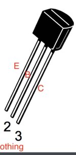
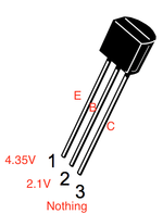
Reset signal is generated from Z4-4, and prior to that Z4-5 and Z4-6. Pin 6 voltage seems okay, but pin 5 is reading all over the place. Back one step at the Q1 PNP (MPSA70) transistor, I'm getting the following readings:

1586178921287.png


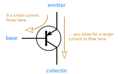
Now not that I have a huge experience with transistors, but taking the following PNP diagram as an example:

1586178983810.png

If I'm getting a voltage at the base, shouldn't I then be getting a reading at the collector (pin 3) ?
 
* 6502 Pin 40 (reset) begins low and stays low. Could this mean that the reset section of the board isn't working?

I've got a new 6502 and some riot chips on order, to test with. They weren't crazy expensive so good to have about anyway.

Step 1: to any cpu board repair make sure you have a good strong clock line (square wave)
Step 2: make sure your reset line starts low then goes high and stays high reliably. Plus there needs to be a small delay between the initial on and then it going high otherwise the cpu will just crash to
Step 3: Buy a logic probe and clear your diary :)


Regarding the ics, please make sure you bought reliable ones and not off ebay unless confirmed as real stock, as otherwise you'll just be chasing your tail forever.
 
Step 1: to any cpu board repair make sure you have a good strong clock line (square wave)
Step 2: make sure your reset line starts low then goes high and stays high reliably. Plus there needs to be a small delay between the initial on and then it going high otherwise the cpu will just crash to
Step 3: Buy a logic probe and clear your diary :)

Regarding the ics, please make sure you bought reliable ones and not off ebay unless confirmed as real stock, as otherwise you'll just be chasing your tail forever.

Thanks for your input Jim much appreciated. Regarding those points...

1. Clock signal tests okay - 3.5Hz at Z3-6 and 900Hz at Z2-9.
2. This isn't happening at the moment, which is why I've been checking the delay & memory protect circuits
3. Probe is bought and lockdown taking care of the diary!

Ebay ICs - point noted.

supplemental point on the reset line. Get a Dallas ic and use that instead. Much better than the gottlieb design. Reset technology has evolved greatly in 35 years
 
Did some more testing of the reset circuit, trying to work out why the reset signal on U1-40 starts low and stays low.

Reset signal is generated from Z4-4, and prior to that Z4-5 and Z4-6. Pin 6 voltage seems okay, but pin 5 is reading all over the place. Back one step at the Q1 PNP (MPSA70) transistor, I'm getting the following readings:

View attachment 104883


Now not that I have a huge experience with transistors, but taking the following PNP diagram as an example:

View attachment 104884

If I'm getting a voltage at the base, shouldn't I then be getting a reading at the collector (pin 3) ?
Looks like a TV perched on top of three cricket stumps. 😬

Always happy to help 😉
🏏

Screenshot_20200406-230845_Chrome.jpg
 
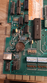
Desolder 20 components from a 40 year old board.. what could possibly go wrong?

I'm going in..

20200406_221221.png

Reset circuit, it's been emotional, but it's time we both moved on.

That moment you realise you have no idea what you're doing:

20200406_230607.png

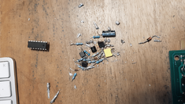
Just waiting on the Dallas reset dohickey now, but this is the result up to that point...


1586211884361.png

In my defence this section of the board was pretty ghetto to begin with.

Anyone got any tips for how to do solder cleanup after a job like this?
 
Last edited:
You should be practicing on old motherboards or something beforehand.
 
To be fair it's not as bad as it looks, just tidy up the soldering. And make sure it's good with a meter.
 
The Dallas reset component thingy arrived today, so I could finish the rebuild of the reset circuit on Robo war.

1587121774031.png

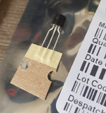
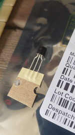
Here the little guy is, masquerading as a transistor. What a kidder.

1587121863746.png

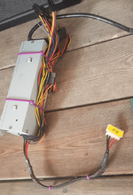
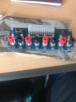
To make things a bit easier I decided to jury rig a 5v source out of an old mini atx power box. You need to connect the 'on' wires together, and it may not look as profesh as those variable bench power sources, but they're 100 quid and this is gangsta.

1587121981497.png

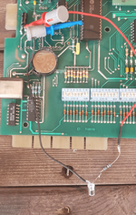
Marco's test ROM installed, and the wee LED on the A6 line to tell me... stuff. Good stuff I hope.

1587122052057.png

Now, let's power this sucker on and see what we get:


Four flashes - i think that means... F$ck me I might have only gone and done it. Let's get it in the machine.


Thankyou to everyone who helped out with their invaluable advice. Great feeling.
 

Attachments

  • 1587121835610.png
    1587121835610.png
    157.5 KB · Views: 4
Last edited:
Back
Top Bottom