What's new

RoadShow lighting circuit problem

davejuk

Registered
Joined
Nov 19, 2015
Messages
125
Location
Bristol, UK
So I finally got around to looking at the various lighting problems on my RS.

Besides a bunch of blown bulbs, I have a whole what appears to be an entire circuit which doesn't work. When I removed a bulb and tested the socket with a multimeter there was a short. So I removed a bunch of bulbs, retested and the short was gone. Some of the 10mm wedge flasher lamps were blackened on the connectors so I would guess one of those was the issue but I was unable to get the short back by reinserting the bulbs. Some of the lamp holders are a bit loose so that's another possibility.

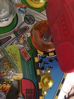
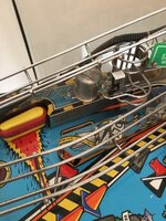
Pics below. These are the lamps that don't work. Where should I start?
 
In the second picture it looks like it's lit but it's not - the light is from a GI bulb below.
 
Hi,

I take it the problem is with the 'flashbulbs' on the rear panel. Six/seven lamps seems a bit much for one flashbulb circuit, and AIR the rear panel has three different drive circuits, each consisting of two lamps the same colour. Does the game have its other flashbulbs working? If so, I'd check if the 20v supply for the bulbs is reaching the back panel.
 
Yes, it's all those 6/7 on the backpanel with yellow/red/white plastic tops.

None of the flashbulbs work and nor do some of the CEC89 type bulbs (not sure what they're called).
 
You should have 20v at each terminal of the flash lamp holder with your black lead on ground braid on a dc scale. If not then you have a blown fuse, possibly one of the five on the rhs of the power board.
 
Ok thanks. I did check all the glass fuses I could see in the back board and they were all fine. Are those the fuses you mean?
 
Ok thanks. I did check all the glass fuses I could see in the back board and they were all fine. Are those the fuses you mean?
Did you pull one side out of the holder and check them with a multimeter ?
 
I checked them with a multimeter without pulling them out... Should I be removing hem to test? There was continuity across the fuse.
 
Yes, if you pull it out or just one end then you're sure the continuity testing is across the fuse and not making a circuit around it somehow.
 
so I finally got around to testing this.

With my black lead on the ground brade, I don't get 20V DC on any of these lamps with my multimeter.

On the flashers on the lower left and right of the playfield I get 1.2V on both terminals.

On the 2 on the upper playfield I get 1.2V on one terminal and nothing on the other (It actually fluctuated wildly in a low range of a few mV)

On all 6 on the back panel I get 1.2V on the red/white terminal but then nothing on the other.
 
Ok let's try again.

With the machine turned off, I have continuity across JETS AT MAX light and the yellow one below the radio (both in picture below).

I also have continuity across the white flasher above the little flipper (picture 2).

Both terminals on all 3 of these lamps are 22.8v dc with my black probe on the ground braid.
 

Attachments

  • image.jpeg
    image.jpeg
    102.4 KB · Views: 8
So the power supply is good, and the lamps are good. They are not being driven. Start by reseating the short grey ribbon cable between cpu and driver.
 
On the upper playfield, the flasher in front of RED and the one to teds right (left playfield), I get the 22.8v dc one one terminal and nothing on the other.

Same in the 6 flashers on the back panel. Here, the 22.8v terminals appears to be the common one (red/white)
 
Ok. Just remembered. Roadshow drives all its flashers from the auxiliary driver board that is at the top right of the back box next to the Dmd board. Check that a. It is present. B. That it's connected c. That the long ribbon cable to the cpu is correctly connected and orientated.
 
Thanks for your help.

In looking at another problem, I swapped out the eddy board for the bulldozer... and the flashers are suddenly working. This may not last so watch this space! Thanks again
 
Ok. Just remembered. Roadshow drives all its flashers from the auxiliary driver board that is at the top right of the back box next to the Dmd board. Check that a. It is present. B. That it's connected c. That the long ribbon cable to the cpu is correctly connected and orientated.

I have the same problem and the long ribbon was connectly around the wrong way and missing out the right hand end pair of connectors. When I corrected it - it blew the Solenoid Secondary fuse rated at 7 Amp time delay and then the Flasher Secondary 5 Amp time delay. Putting the lead back as I found it the machine is usable - Can you please advise anywhere I should look next? Thanks.
 

Attachments

  • IMG_2372.jpg
    IMG_2372.jpg
    102.5 KB · Views: 11
Last edited:
Back
Top Bottom