What's new
Pinball info

Register a free account today to become a member! Once signed in, you'll be able to participate on this site by adding your own topics and posts, as well as connect with other members through your own private inbox!

Replacing Stern Insert LED

MarkS

Site Supporter
10 Years
Joined
Oct 14, 2013
Messages
287
Location
Devon
My GZ arrived with the "Again" of "Shoot Again" inserts not lighting up - I tested the light using the Diagnostics menu just to be sure, so then figured I'd need to take a look inside. It would seem this is not as simple as replacing an olde fashioned bayonet bulb so I figured best to check before I break something...! :)

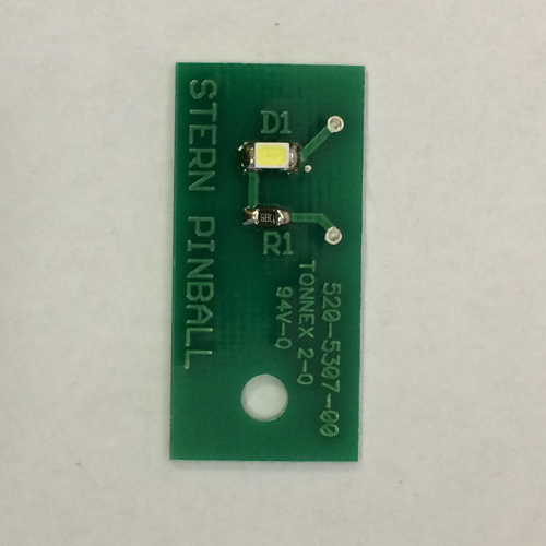
So the wires seem soldered OK. Presumably I can unscrew this little board, but is the bulb replaceable and if so what do I need to buy and from where please? Or is it integral to the board and non-replaceable (surely not?)?

Also, as I'm scrabbling around using tools that aren't quite right, is there a specific tool people use to remove these? What size nut driver or spanner would this be, or can I just use a screwdriver?

Thanks!

1666346588917.jpeg
 
Looks like a standard 1/4" driver should do the job?

The LED will be a surface-mount component. Not terribly hard to change but will require soldering. Alternatively a whole new board. Suggest reflowing the various connections in case there is a dry joint. Also maybe swap with another similar board in the game? Last but not least...could the wires be soldered the wrong way round?! 🤦‍♂️
 
This is the part from pinball.co.uk, not sure if the b on the end of the part number denotes anything different.


I would unbolt it and test with a multimeter with the test on the make sure power was getting to it and is the right way round as Fubar suggested, probably cheaper to replace than try and repair at that sort of price, although postage probably doubles the price.

And as above being USA made would expect any hardware on their to be imperial sizes.
 
Thanks for the replies and help. I will order some nut drivers and look at multimeters (having never used one before if anyone wants to suggest a particular type I'd appreciate it, think "rank amateur who doesn't want to electrocute himself" as a starting point :))

I'm also assuming that "dry joints" or "replacing the PCB" are both going to involve something with a soldering iron which I don't have either...

I looked up the light in the GZ manual (p18) - see photo below - but how do I know which connection point is for the source wire and which is for the return wire on a PCB? That must be a dumb question but really I can't work it out :hmm:

1666380531837.png
 
Your going to need a soldering iron to fix it.

Having a look at that light reference and checking the service manual I think Fubar called it with his last idea, it looks like the wires have been soldered onto the wrong pads on the Led board.

Red should be 5v and the orange/brown is the gnd, in your picture they are the other way round.

Have a check on the one that works to see which way round they are to confirm.
 
Get whoever sold it you to send out another PCB. You can not really replace the LED unless you can solder half decently.

If it is Phil Palmer you have a 2 year warranty.

If its not Phil and you get no joy of the company you purchased it off, call electrocoin.

You will need a soldering iron and you can not get the wires the wrong way round.

To get the nut out, use one of those screw drivers you can change the ends in, those are 1/4 inch.

Here is an example, but many are around - I bet you have one. Just remove the bit.

https://www.amazon.co.uk/STANLEY-Multibit-Ratchet-Screwdriver-Bits/dp/B0001IW7OS/ref=sxin_17?asc_contentid=amzn1.osa.451e0260-aef1-4e30-94b2-03275a6cec33.A1F83G8C2ARO7P.en_GB&asc_contenttype=article&ascsubtag=amzn1.osa.451e0260-aef1-4e30-94b2-03275a6cec33.A1F83G8C2ARO7P.en_GB&content-id=amzn1.sym.b5c831cd-6cc6-43ae-a983-386a9534fba5%3Aamzn1.sym.b5c831cd-6cc6-43ae-a983-386a9534fba5&creativeASIN=B0001IW7OS&crid=224CKJ8BV2DWB&cv_ct_cx=multi+screwdriver&cv_ct_id=amzn1.osa.451e0260-aef1-4e30-94b2-03275a6cec33.A1F83G8C2ARO7P.en_GB&cv_ct_pg=search&cv_ct_we=asin&cv_ct_wn=osp-single-source-all-asins&keywords=multi+screwdriver&linkCode=oas&pd_rd_i=B0001IW7OS&pd_rd_r=512b99d0-1d97-4921-bc10-f41e1e677e82&pd_rd_w=P4fg5&pd_rd_wg=SnrpC&pf_rd_p=b5c831cd-6cc6-43ae-a983-386a9534fba5&pf_rd_r=V8065V2RKTPTYHDZJEX1&qid=1666426461&qu=eyJxc2MiOiI2LjE3IiwicXNhIjoiNS41MCIsInFzcCI6IjUuMDYifQ%3D%3D&sprefix=multi+screwdriver%2Caps%2C79&sr=1-1-887d48f0-d798-4604-a3e5-14d9d204cf06&tag=lionshomeospu-21
 
You will need a soldering iron and you can not get the wires the wrong way round.

Would you care to elaborate on that statement, its an LED light, it will only work with the polarity the correct way round with the positive voltage on the positive pad and ground on the negative pad, if you try and run power the wrong way round through an LED it will not light up, the statement would be correct if it was an incandescent light.
 
Ground and positive are marked on the boards, just copy what you've got in the machine, you'll be fine.
 
Ground and positive are marked on the boards, just copy what you've got in the machine, you'll be fine.
Yeh i wouldnt in case it's wired wrong from the factory.... wouldnt be the first time...

I would fire up the machine, select test on that LED, and see which way around they are using a meter (and make sure that corresponds to the markings on the LED board...). It doesnt work for a reason.... so either it's wired incorrectly and managed to make it past the QC (which wouldnt be unusual for Stern), or somethings just blown it...
 
Thanks for all the further help and explanations - seems to me it's been wired wrong, that's quite the QC from Stern :rolleyes:

It was NIB from PH so I can revert to Phil if there's anything more wrong than that, I just wanted to understand what it could be and things I should be checking. I have a friend visiting in a few weeks who is going to bring a multimeter and soldering iron and teach me the basics to check the voltage etc - it's something I need to start learning really.... at least it's nothing important that stops me from playing!
 
So with the help of someone who knew what they were doing, we unsoldered the existing wires and soldered them back the correct way (thanks Stern QC) - I also learnt what a dry joint was as we then had to re-flow some new solder onto one of the wires :cool:

He also pointed out that the 'D' of LED refers to the diode which controls the directionality of the current which is why the wiring matters. Sorry this is probably obvious to most people but hopefully will be useful to someone else who stumbles across this thread one day!
 
Do stern manufacture these boards in house or do they use a PCBA house? Also id be very suppressed if they was not assembled via a PNP machine so crazy it was soldered on backwards! Maybe came in the packaging that way? I think PNP machines assume the component is in the correct orientation in the tape and blindly just sticks in on the board?
 
My guess is they get the PCBs manufactured & assembled but solder the wiring harness on (red/orange wires in OP) in-house -- and that's when they got swapped.
 
My guess is they get the PCBs manufactured & assembled but solder the wiring harness on (red/orange wires in OP) in-house -- and that's when they got swapped.

I would say this is correct, pretty sure Ive seen on a tour video that someones job is just to sit there and crimp the pins on wires, and thats all they do all day, and with that being done in house I would expect there is another job role that someone sits there and assembles the sub looms by putting the pins in the plugs and soldering the wires to the LED boards, so with them doing jus that for their shift all day I would expect you to get the odd one not right every so often.
 
Back
Top Bottom