What's new
Pinball info

Register a free account today to become a member! Once signed in, you'll be able to participate on this site by adding your own topics and posts, as well as connect with other members through your own private inbox!

Repinning advice please

cooldan

i like pizza
Joined
Jul 21, 2011
Messages
6,456
Location
Ealing, London
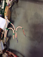
Hey guys, if you know me on Facebook you may have seen me having some troubles with voltage that disappears on a CFTBL so I'm gonna replace the header pins and molex the connector.

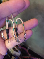
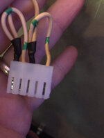
But how do I replace this gubbins?
And do I even need to, looking at this schematic, or can I just attach the two input wires to pins 1 and 5?
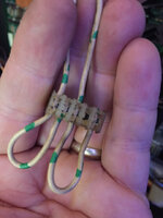
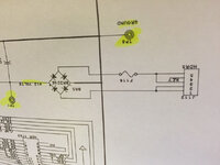
uploads.tapatalk_cdn.com_20160612_d2f9e0f0f9dfff32865501392ba0899c.jpguploads.tapatalk_cdn.com_20160612_132f3301ff42c6087bfa734e9e526481.jpg

I also have a question about a loose wire floating inside the coin door that may need someone with a Creech to do a comparison for me -
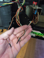
uploads.tapatalk_cdn.com_20160612_43ffa2166919cf13fc475e32a28cf861.jpg

Should these two be connected (orange/black and green + orange/silver) or does it not matter?
 
yeah there's still a coin mech and the green goes there, but i'm wondering if the two orange wires should be connected, as they both come out of the pipe leaving the coin door, and both go nowhere, not sure if they shoulda been joined at one stage and maybe i broke the bond by accident. the diagnostic buttons are all cruddy and i can't tell if one or both of these orange wires should be going there too.

but the molex repinning question - do i need to fashion some weird loops or can i ignore pins 2 and 3?
 
ok thanks Peter, good advice.

from a practical perspective, how should i physically prepare the wires for molex, any tips on that?
two wires need to go into 4 molex terminals
 
yeah there's still a coin mech and the green goes there, but i'm wondering if the two orange wires should be connected, as they both come out of the pipe leaving the coin door, and both go nowhere, not sure if they shoulda been joined at one stage and maybe i broke the bond by accident. the diagnostic buttons are all cruddy and i can't tell if one or both of these orange wires should be going there too.

but the molex repinning question - do i need to fashion some weird loops or can i ignore pins 2 and 3?
Do the buttons all work? There should be an orange wire going to each one. So 4 oranges. And one other that goes to one switch and then is sometimes (?) daisy chained to the other 3. You look like you got 4 oranges there.
 
ok thanks Peter, good advice.

from a practical perspective, how should i physically prepare the wires for molex, any tips on that?
two wires need to go into 4 molex terminals

You just crimp 2 wires in the first pin and the second wire into the next pin and do the same for the other double pin
 
Yes mate. I'm trying desperately to jazz up the description but in truth, I can't !! But if you need one......
 
  • Like
Reactions: JT.
No need to go to all that hassle of stripping ends and soldering.

Just get a;

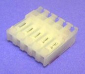
.156" (3.96mm) IDC 5-Position Connector For 22 Gauge Wire
View attachment 31488

and 'push' in with an IDC insertion tool;

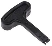
View attachment 31487

http://tinyurl.com/hezzdlu
In this case I think Dan wanted to molex/crimp rather than IDC.

It's not much hassle to prep the cable and crimp. And at the risk of restarting the IDC vs Crimp war..... :-D..... arguably provides a better connection.
 
Back
Top Bottom