I've had a few resets on Hurricane of late, so I followed Pinwiki. Such an amazing resource.
I've done all the non invasive stuff.
I have moved down the pinwiki to the more advanced stuff. I have good kit and had some success with fixing a few parts on boards, so I thought I'd progress.
But I have run into a problem that I cant fathom on my own and I wondered if by documenting it here, someone might be able to guide or help me.
I'm keen to understand, hence why I haven't sent the board off to someone.
Symptom
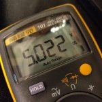
When I turn on, I get no 5v on TP and nothing on the VOut of the PSU5. I get 12v on the VIn pin, as measured from the top side of the board when installed.
DMD has scrambled dots, no lamps lit on the machine, no CPU LEDs
I assume as we have no 5v.
Whats occured?
I replaced J114, J115 and J120 headers that were burnt. Board went back in, all good.
I reflowed J101 and J102 as it looked very tarnished there, board went back in, all good. I suspect I should have changed those while I was there.
I replaced C2, C4, C11, C5. Board back in, all good. No lost traces, nice clean through holes, correct polarity.
All worked well, attained a lift in 5v to 4.95v pretty steady.. But still occasional resets. Obviously this could be many things, but as I am changing elements out, I continue.
I replaced LM323K with a new PSU5 No noise - Machine fires up, but has no 5v. All other voltages seem present and correct
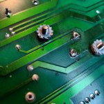
When I removed LM323 there was a fair bit of solder around the two bolts that hold it in place. These provide GND to the PSU5 (as they provided GND to the body of the LM323 before it). My new bolts and serrated nuts are in and I get GND continuity between the two bolts and the GND on the board. Could this blob have been put there to get over a GND issue in the past? But if it was, I have now tested and found GND on the bolts AND on the PSU5 board itself. So I think thats ok, both sides.
I've soldered the VIn and VOut cleanly. Continuity both sides to elsewhere on the board. I'm wondering if I am missing something on this part. Maybe there isn't enough connection on the parts side of the board, I cant see that, but I dont know if its mean to have connection that side or not. I know both pins connect on solder side of board.
I DID have an issue when I first put the board back under power, one of these bolts DID NOT have a good GND. Could turning it on with one of them not having a good GND, kill something else? Ive tried two PSU5s.
I am following the power on schematic.
I have checked J101 (1&2) I have 10vac there, around what I expected
I have checked the + leg of BR2 - I have 12.6v there. I wasn't expecting it to be that high there. More like 9v or thereabouts. Wondering if this is a point of investigation?
C5 is new, tested as working in the game before this switch out. Maybe I've damaged this?
Maybe I've damaged C9, I don't know how to test that
VIn has 12.6v on the top side of the pin.
I HAVE noticed I get GND continuity on the VOut pin of the PSU5. I was NOT expecting that, but I don't have the electrical understanding to know if that's an issue, or if when in circuit continuity can be found because of the circuit it is in?
I've tried 2 x PSU5s, same result.
I might go back to the old LM323 to test on that.
But the failure 'seems' to come on the PSU5 VOut, as its being fed 12.6VIn but not outputting anything.
Did I damage the PSU5 with the no GND issue?
I appreciate this is all self inflicted, but I've come along way!
Rob


