What's new
Pinball info

Register a free account today to become a member! Once signed in, you'll be able to participate on this site by adding your own topics and posts, as well as connect with other members through your own private inbox!

Power board repairs and or replacement

Jagspete

Registered
Joined
May 27, 2019
Messages
655
Location
Macclesfield
Alias
Aka Pete
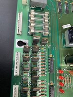
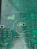
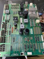
So picked up the Sega SW from south coast which wasn’t booting. Going thru wiring and connections before attempting to turn on and found some missing and loose ( poorly soldered) components on the power board, once removed found some dodgy repair work and ‘chicken ****’ soldering. I’m only just starting to do board work, removing and replacing resistors so far, so have a few questions...1. What causes the failures that have led to these ‘repairs’, 2. if I swap in a working power board from my starship troopers will it be damaged, 3. would the damaged board be repairable. 4 And also the ‘bridged wires’ .. why and where to?2B450F2F-9AAC-4AE6-BC86-6204223E7A99.jpeg9BCF00C5-5991-419E-87D4-712FCAB3816A.jpeg87F6ED6D-5DBF-45A7-82F6-46E064705693.jpeg
 
Looks like some pretty terrible work there. Likely motivation was blown transistors - pretty common.

The jumper wires might have been added because whoever did the board work messed up and destroyed a trace. There can be legitimate reasons to add these (creating a lower impedance path), but considering the quality of the work here I wouldn't assume anything...

Get it nice and clean with lots of isopropyl alcohol. Check for continuity of the traces which look dodgy. Check for blown transistors using diagnostics and replace as needed...

Good luck!
 
Thanks Fubar. So removed the jumper wires and stripped and resoldered the bridge connector and the capacitor which had the dullest unflowed solder. Tried my best with the 3 bodged in transistors but the eyelets (thru holes) in board had been stripped out, and some of the traces lifted and damaged, but at least I do have continuity on everything now. Will try and test it in my SST tomorrow.
 
I'm not sure how you'd go around re-plating a via. If the traces are fubar'd you may need to run some jumper wires to the transistor legs (and hold the transistor on with some goop).

Beware: if you have continuity but the trace is damaged, it may not be safe to pass too much current through it... A heat camera can be useful here.
 
Not uncommon for people who haven’t got a clue to damage boards when they try to swap blown or non working parts. Small pads and the way parts are sometimes factory installed with bent over legs can cause issues for people if they don’t have the right tools or the right solder or use the right temperature settings. Operators back in the day didn’t give a **** either and would often bodge stuff badly just to keep them going.

my advice is give the board to someone who knows what they are doing if you don’t! An original board can last a lifetime and remain factory if looked after and repaired properly.
 
So power board went into SST and hey presto all working.... game starts.... but no flipper , slingshot or bumper power! Back to drawing board thought I ,so put SST power board back in, and still no power in gameplay, no coils would work in test either. Checked all my fuses, remade connections etc. Then noticed one of the leds blinking, think it was 204, which gets its power from j1 ribbon cable, turns out one of the pins on the mpu was corroded, once cleaned up and new ribbon cable fitted everything worked with both boards now.
 
That's because the driver board had no data being received and so the watchdog was timing out in a loop (barking). Its a safety feature so the driver board can't be locked on and fry coils,/burn up if the main cpu board stops running or crashes. the led flashes as the reset chip resets each time the watchdog expires.

Very intelligent design.
 
Usually people can not unsolder components correctly and end up on these boards especially taking up the pad and tracks.

Also on some boards components can get that hot they physically damge the PCB.

Most used pins I come across have something like this on them.

GI soldered directly to pins on WPC boards, legs chopped off the old transistors/mosfets and new ones soldered onto those legs as someone could not be bothered to take the PCB out.....

Anyhow - keeps me in work......
 
Back
Top Bottom