What's new
Pinball info

Register a free account today to become a member! Once signed in, you'll be able to participate on this site by adding your own topics and posts, as well as connect with other members through your own private inbox!

Possible Ground Braid Issue?

Wiredworm

Registered
10 Years
Joined
Apr 7, 2013
Messages
2,377
Location
Grimsby
Hi,

I've recently been doing some work on my R&B Pinball and need to take some voltage readings from various components on the playfield.

As we're working with DC current my understanding is that the black terminal should connect to the ground braid and then I can use the red probe to read voltages at the required points on the playfield.

Now, here's the strange thing.

When I do this I get very little in the way of readings. For example taking a reading on the relay board which controls the saw motor shows currents of < 1v.

However, if I move my black terminal to the ground point on the CPU board then I get correct readings (> 40v on the relay board).

I've checked continuity from the ground braid to the earth pin on the plug and it checks out.

Has anyone got any clues what's going on here?

Thanks in advance

Pete
 
I've taken readings both at the relay and also at the motor connector too, but the issue is the same with both. No (or very low) readings if black is on the ground braid, but what I believe to be correct readings when black is on CPU ground.

The readings i've got:

Relay: Idle
Coil: 15v
Dry: 41v
28+: 41v
Gnd: 0v

Relay:Active
Coil: 15v
Dry: 0.8v
28+: 40v
Gnd: 15v

Motor Connector: Idle
White: 0v
White/Red: 19v

Motor Connector: Active
White: 17v
White/Red: 19v

The issue with the voltage readings actually came to light because the motor i've got is brand new (Dan bought it before he passed the table on to Matt) but it's not working. It's labelled up as needing a 24v DC supply so i'm trying to figure out where the problem lies. The 41v on the relay doesn't look right to me, but I could be wrong.

One thing I did note last night is that there's a 4 pin molex connector feeding the relay and one of the pins actually has two wires inserted into it. Again, not sure if it's meant to be that way or not.
 
I don't think there's a voltage interlock because all of the coil tests fire with the door open or closed.

Although I have taken readings with the door both open and close just in case that was the issue.

I should also perhaps add that the motor not working is a secondary issue right now. The thing that's really bugging me is why I can't get a reading when using the ground braid as earth. Answers on a postcard etc. etc. ;)
 
Probably the ground-braid is connected to earth (in the domestic plug) and to the transformer casing but is isolated from the digital 0v.
 
Ok, sorry if this is a stupid question, but i'm assuming that's not how it should be?

If that's the case then how would I go about checking and/or rectifying the issue please? Been a long time since I did my basic electronics training and i'm pretty new to the world of Pinball. :-)
 
Yeah lots of early ss gottlieb games had different earths which caused a lot if problems and need to be rectified when fixing games.
 
Check that the ground plane to which all the boards are screwed Is grounded to the earth braid somehow. Usually around the lower left hand side, along with the earth to the speAker panel
 
Thanks Andy, i'll check that out when i'm back home tonight.

When you say boards are we talking about the ones in the back box or those mounted under the playfield? Or both?
 
Cheers Andy. I'll check it out.

Should there be a connection from the back box to the earthing braid? I had to strip the head to get it in the house when it arrived and i'm wondering now if i've missed something when reconnecting.

Although strangely the ground point on the CPU board works fine.
 
The earth braid should run round the cabinet including the back box - check for continuity between the two. It will work with the CPU ground anyway because as well as having an earth braid because the 0v supply to the boards is from the transformer.
 
Thanks Xenon. I'll take a look tonight. It's possible i've missed something when reconnecting the head.
 
Thanks for all the help guys - got to the bottom of it.

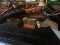
The cabinet has had a new back installed at some point and as a result of this the mechanism used to secure the head isn't the usual alan bolt but instead two wing nuts screw down from above. This means the bottom half of the securing mechanism isn't there any my guess is that the braid would usually be connected there so it's bridged up to the back box.

You can clearly see the top half of the assembly here:

20130627_164036.jpg

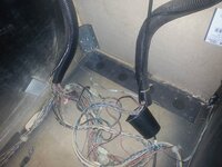
The slightly amusing story here is that it took me absolutely ages to figure out how to plug the darned machine in. When it arrived it came with a seperate cable, but for the life of me I couldn't find a socket that would accept the cable. Turned out the cable wasn't even related to the table and in fact the cable and plug were coiled up in the body of the machine. But when they'd installed a new back they didn't cut a hole or connect up the cable cup so right now the power cable is looped up to come out between the back box and the body (you can barely see it in the shot above).

The ground braid just runs along the bottom of the cabinet like this:

20130627_163902.jpg

So, a few questions now:

1. Do I need to replace the entire braid or can I simply add sections where needed. I'm guessing if I can add sections then it makes good sense to securely staple the overlaps and make sure there is a reasonable overlap to prevent it slipping or coming off?

2. It would make sense to secure the braid to the rear of the cabinet and then run a new segment up that should be screwed under the same terminus as you can see in the first picture? Obviously the only issue with this is I need to remember to disconnect it if I want to remove the head.

3. I need to cut a hole for the cord cup. Not sure how that connects to the back of the cab - does it fit directly or is there some kind of coupling ring normally?

Thanks for the help so far. To prove the theory I hooked a cable up from the ground braid to the top box braid shown in the first picture. Then I did my meter test using the method that was showing zero volts and now I get correct readings.

Pete


Pete,

You just need to carry on from an existing Braid to the backbox - there is usually an earthing point on the bottom of the backbox (to the left - just a "stud" that stucks up with a nut on it). As long as there is a good earth from the cab, and this is connected to the earth from the head, you;re in business...

The cord cup should have 4x holes on the one end - cant see from your pic - these would screw into the back of the machine once the hole is drilled.... I'll try to find a pic....
 
Thanks Paul,

There's actually a number of earthing points on the backbox on this machine. Both the left and right speakers have seperate earthing straps which go to a post either side with a wing-nut holding them in place.

Then in the middle where the old locking mechanism is there's a braid which runs up to the main metal plate to which all the PCB's are fitted. So my guess is that I can actually take my braid to any of those points. In fact it's most likely i'll go straight to the middle as it's the most visible and direct route.

Before doing so i'll tack the braid that's in the cabinet back to the rear instead of just having it loose in the bottom. That way I can then put a short run straight up from that to the backbox.

I'll take a look at the cord cup over the weekend when i've got the playfield lifted. :-)
 
And of course the million dollar question.

Where in the UK can I actually pick up ground braid? I know Marco sells it but it seems a bit stupid shipping it over from the US for the amount I need. I'd estimate I only need a few feet.

And can anyone advise me please on fitting it in place - I believe it's meant to be stapled but is there a recommended type of staple/staplegun to use?

Thanks

Pete


Pete - Drop me a PM with your address and how much you actually need.... I'll get some in the post to you.

If you want more, you can get it from Rapid Electronics.....

http://www.rapidonline.com/Cables-Connectors/Flat-Braid-Flb-2-5-36-25m-Reel-03-1926

Paul
 
Thanks Paul - that's really appreciated.

I'll drop you a PM.

I'll make a note of that link although with only a single Pin I can't see me needing it for the moment. ;)
 
Paul, how much do you estimate I would need for a complete SS machine?

Someone told me I think it was around 10m, however I'm not sure. I'll do my Addams this weekend and see how much I have left (else I'll need to get some more for FT too)

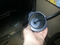
Oh, and I think I need to pick up a new cord cup. Ooops.

View attachment 2419


The cup thingie not the cord - the cord looks fine - you just take the plug off, feed it back through, put the replacement on and re-wire the plug - done :)
 
Thanks Paul.

I might as well get that done when i'm doing the braid as i'll need to disconnect and remove the playfield anyway in order to do the job as neatly as possible. Might well use the chance to have a bit of a cleanup inside the cabinet too.

It's one of these I need: http://www.marcospecialties.com/pinball-parts/545-5122-00

Anyone know of a uk stockist please?

When fitting the cord cup screws to the inside of the cabinet - correct?

Pete

Edit: And I might look at replacing the right rear leg plate too. That's the area where theres some bad chewing on the outside of the cabinet so I may well use one of the larger plates to make sure it's good and strong.
 
Back
Top Bottom